TM 5-3805-290-23-1
ELECTRICAL SYSTEM TESTS, INSPECTIONS, AND ADJUSTMENTS - CONTINUED
0013 00
DIGITAL THROTTLE POSITION SENSOR CIRCUIT TEST - CONTINUED
8.
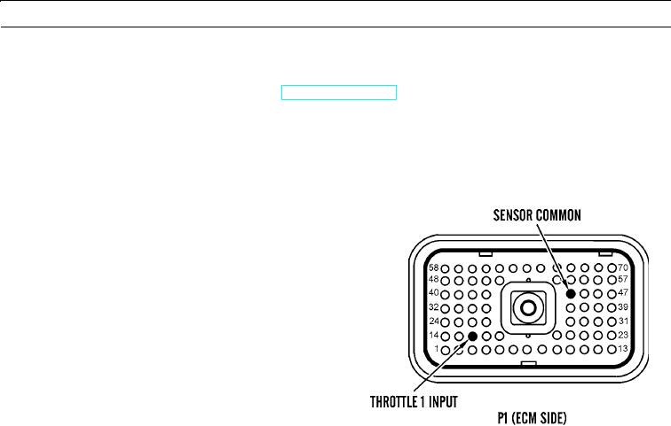
Check throttle position sensor at ECM.
a.
Turn engine start switch to OFF position (TM 5-3805-290-10).
N OT E
Use 70-pin breakout T. This eliminates the need to disassemble ECM P1. If available, measure PWM signal
between P1:16 and P1:44.
b.
Disconnect P1 from engine ECM (WP 0053 00).
c.
Remove terminal 16 from P1.
d.
Connect P1 to engine ECM (WP 0053 00).
e.
Connect multimeter to terminal 16 and a chassis
ground.
f.
Turn engine start switch to ON position (TM 5-
3805-290-10).
g.
Use multimeter to display output signal of throt-
tle position sensor while engine speed control is
moved from minimum position to maximum
427-B0674
position.
h.
Turn engine start switch to OFF position and
connect terminal 16 to P1 connector.
i.
Expected Results. Position should be between 10 and 22 percent in low idle position. Position should be between
75 and 90 percent in high idle position.
(1)
If results are OK, ECM terminals have correct signal for throttle position sensor. Check for proper supply
voltage at ECM. If voltage is correct, then ECM is suspect.
Replace engine ECM (WP 0053 00). Verify repair eliminates problem.
(2)
If results are NOT OK, a fault exists in harness or connectors between sensor and ECM. Check terminals
between machine interface connector and throttle position sensor. Replace wiring harness in question (WP
0169 00 thru WP 0175 00). Verify repair eliminates problem.
0013 00-24

