TM 5-3805-290-23-1
ELECTRICAL SYSTEM TESTS, INSPECTIONS, AND ADJUSTMENTS - CONTINUED
0013 00
DIGITAL THROTTLE POSITION SENSOR CIRCUIT TEST - CONTINUED
d.
Expected Results:
(1)
If MSD displays 91-08 or 774-08, proceed to step 3.
(2)
If MSD displays 41-03 or 41-04, proceed to step 5.
(3)
If MSD displays no active diagnostic codes, proceed to step 7.
3.
Check throttle position with MSD.
a.
Connect MSD to diagnostic connector (WP 0006 00).
b.
Turn engine start switch to ON position (TM 5-3805-290-10). Engine should be OFF.
c.
Observe throttle position reading on MSD.
d.
Press and release throttle.
e.
Expected Results:
(1)
Output should be 0 percent when pedal is released. Output should increase to 100 percent when throttle
pedal is fully pressed.
(2)
Output should be between 20 and 27 percent at low idle position. Output should be between 80 and 87 per-
cent at high idle position.
(a) If results are OK, throttle position sensor is operating correctly. Proceed to step 5.
(b) If results are NOT OK, ECM is not receiving correct signal from sensor. There may be problem in
harness. Proceed to step 4.
4.
Check voltage at throttle position sensor (WP 0039 00).
a.
Turn engine start switch to OFF position (TM 5-3805-290-10).
b.
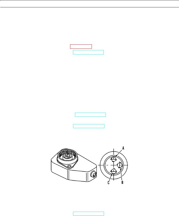
Install breakout T with three terminals for this test procedure.
c.
Turn engine start switch to ON position (TM 5-3805-290-10).
d.
Measure voltage between terminal A and terminal B.
e.
Remove breakout T and reconnect throttle position sensor.
427-B2058
f.
Expected Results. Supply voltage should be between 7.6 and 8.4 VDC.
(1)
If results are OK, supply voltage is reaching sensor. Proceed to step 5.
(2)
If results are NOT OK, proceed to step 6.
5.
Disconnect throttle position sensor and check for active diagnostic codes.
a.
Turn engine start switch to ON position (TM 5-3805-290-10). Use MSD to check for active diagnostic codes.
b.
Ensure 41-03 or 41-04 is displayed on MSD as an active diagnostic code.
c.
While throttle position sensor is connected and disconnected, monitor MSD screen. Check and record active diag-
nostic codes.
0013 00-22

