
TM 5-3805-290-23-1
ELECTRICAL SYSTEM TESTS, INSPECTIONS, AND ADJUSTMENTS - CONTINUED
0013 00
ELECTRICAL POWER SUPPLY CIRCUIT TEST - CONTINUED
1.
Inspect electrical connectors and wiring.
a.
Disconnect and thoroughly inspect harness connector J1/P1. Also inspect connections for battery and connections
to engine start switch. Refer to Electrical Connectors Inspection (WP 0022 00, WP 0077 00, WP 0053 00, and WP
0169 00).
b.
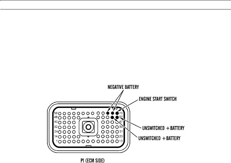
Perform 10 lb (45 N) pull test on each wire in ECM connector associated with these connections:
(1)
P1:48, P1:56, and P1:57 (unswitched +battery)
(2)
P1:61, P1:68, and P1:69 (-battery)
(3)
P1:70 (engine start switch)
427-B0703
c.
Check ECM connector (socket-head screw) for proper torque of 55 lb-ft (6 Nm).
d.
Check harness and wiring for abrasions and pinch points from battery to ECM. Also, check harness and wiring for
abrasions and pinch points from engine start switch to ECM.
e.
Expected Results. All connectors, pins, and sockets should be completely connected and/or inserted. Harness and
wiring should be free of corrosion, abrasions, and pinch points.
(1)
If results are OK, reconnect all connectors and proceed to step 2.
(2)
If results are NOT OK, replace wiring harness in question (WP 0169 00 thru WP 0175 00). Ensure all seals
are properly in place and connectors are securely connected.
0013 00-30