TM 5-3805-290-23-1
ELECTRICAL SYSTEM TESTS, INSPECTIONS, AND ADJUSTMENTS - CONTINUED
0013 00
ELECTRICAL POWER SUPPLY CIRCUIT TEST - CONTINUED
2.
Check battery voltage at ECM
a.
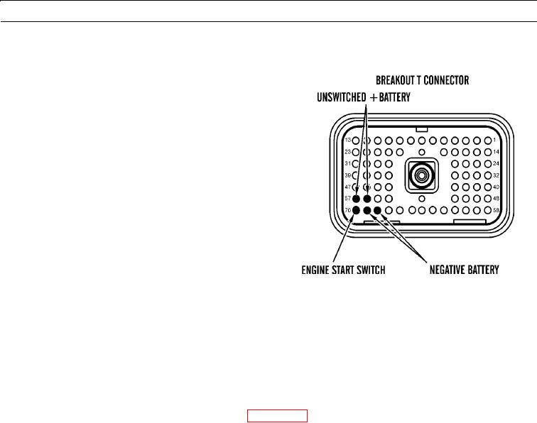
Disconnect engine harness connector P1 from
ECM connector J1 and insert breakout T (WP
0053 00).
b.
Connect harness to breakout T and breakout T to
ECM.
c.
Turn engine start switch to ON position (TM 5-
3805-290-10).
d.
Measure voltage between P1:56 (unswitched
+battery) and P1:68 (-battery).
e.
Measure voltage between P1:57 (unswitched
+battery) and P1:69 (-battery).
427-B0704
f.
Expected Results. Measured voltage is between 22 and 27 VDC with no suspected intermittent problems at this
time.
(1)
If results are OK, ECM is receiving correct voltage.
(2)
If intermittent condition is suspected, refer to Electrical Connectors Inspection (WP 0022 00).
(3)
If battery voltage is out of range, proceed to step 3.
(4)
If there is intermittent or no voltage, proceed to step 4.
(5)
If engine start switch voltage is out of range, trace wiring for engine start switch from ECM through
engine start switch circuit to batteries (WP 0210 00). Find problem and replace wiring harness in question
(WP 0169 00 thru WP 0175 00). Verify repair eliminates problem.
3.
Check batteries.
a.
Measure no-load battery voltage at battery posts.
b.
Load test batteries. Refer to TM 9-6140-200-14, Operator's, Unit and Direct Support and General Maintenance
Manual for Lead-Acid Storage Batteries.
c.
Expected Results. Batteries pass load test. Measured voltage is within specification.
(1)
If results are OK, replace wiring harness in question (WP 0169 00 thru WP 0175 00). Ensure all seals are
properly connected.
(2)
If results are NOT OK, recharge or replace faulty batteries (WP 0077 00). Verify repair eliminates prob-
lem.
0013 00-31

