TM 5-3805-290-23-1
ELECTRICAL SYSTEM TESTS, INSPECTIONS, AND ADJUSTMENTS - CONTINUED
0013 00
FUEL TRANSFER PUMP CIRCUIT TEST - CONTINUED
4.
Ground input to power relay at MIC.
a.
Turn engine start switch to OFF position (TM 5-3805-290-10).
b.
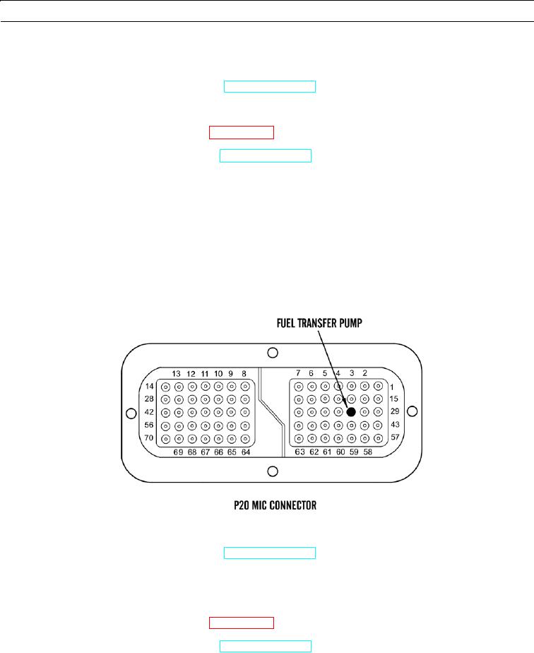
Disconnect P20 connector from MIC and connect 70-pin breakout T (WP 0170 00).
c.
Connect MSD to diagnostic connector (WP 0006 00).
d.
Turn engine start switch to ON position (TM 5-3805-290-10).
e.
Use override setting in MSD to engage fuel transfer pump.
f.
Measure voltage between P20:31 fuel transfer pump control and socket 69 NEG battery on breakout T.
g.
Expected Results. Voltage is 0 when fuel transfer pump is engaged.
(1)
If results are OK, proceed to step 5.
(2)
If results are NOT OK, problem exists in wires between fuel transfer pump power relay and MIC. Replace
wiring harness in question (WP 0169 00 thru WP 0175 00). Verify repair has eliminated problem.
427-B0900
5.
Ground input to power relay at ECM connector.
a.
Turn engine start switch to OFF position (TM 5-3805-290-10).
b.
Remove 70-pin breakout T and connect P20 MIC (WP 0170 00).
c.
Disconnect P1 ECM connector from ECM and connect 70-pin breakout T (WP 0053 00).
d.
Connect MSD to diagnostic connector (WP 0006 00).
e.
Turn engine start switch to ON position (TM 5-3805-290-10).
f.
Insert jumper wire between J1:31 on breakout T. Monitor status screen on MSD. Slowly connect and disconnect
other end of jumper wire to socket 69 NEG battery on breakout T.
0013 00-61

