TM 5-3805-290-23-1
ELECTRICAL SYSTEM TESTS, INSPECTIONS, AND ADJUSTMENTS - CONTINUED
0013 00
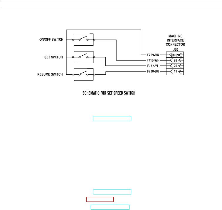
SET SPEED CIRCUIT TEST - CONTINUED
427-B0910
1.
Inspect electrical connectors and wiring. Refer to Electrical Connectors Inspection (WP 0022 00, WP 0052 00, WP
0053 00, and WP 0077 00).
a.
Turn engine start switch to OFF position (TM 5-3805-290-10).
b.
Disconnect and thoroughly inspect ECM connector J1/P1, MIC J20/P20, and battery connections.
c.
Check harness and wiring for corrosion, abrasions, and pinch points from throttle switch to ECM.
d.
Reconnect all connectors.
e.
Expected Results. All connectors, pins, and sockets should be completely inserted and connected. Harness and wir-
ing should be free of corrosion, abrasions, and pinch points.
(1)
If results are OK, proceed to step 2.
(2)
If results are NOT OK, replace wiring harness in question (WP 0169 00 thru WP 0175 00). Verify repair
eliminates problem.
2.
Check SET SPEED switch on MSD.
a.
Turn engine start switch to OFF position (TM 5-3805-290-10).
b.
Connect MSD at diagnostic connector (WP 0006 00).
c.
Turn engine start switch to ON position (TM 5-3805-290-10).
d.
Observe status of set speed switch on MSD while operating set speed switch from Speed 1 position to Speed 2
position.
e.
Observe status of set speed switch on MSD while operating set speed switch from ON to OFF.
f.
Observe status of set speed control Set/Resume switch while operating switch from OFF to ON position.
g.
Expected Results.
N OT E
If engine application has two engine speed controls, ensure Speed 1 is selected.
(1)
MSD shows that set speed control switch is in OPEN condition when set speed control switch is in OFF
position. MSD shows that set speed switch is in CLOSED position when set speed switch is in ON posi-
tion.
0013 00-63

