TM 5-3805-290-23-1
ELECTRICAL SYSTEM TESTS, INSPECTIONS, AND ADJUSTMENTS - CONTINUED
0013 00
SET SPEED CIRCUIT TEST - CONTINUED
f.
Expected Results. Measured resistance should be less than 10 Ohms with switch ON. Measured resistance should
be more than 2,000 Ohms with switch OFF.
(1)
If results are OK, proceed to step 6.
(2)
If results are NOT OK, a problem exists with wires between suspect switch and P20 connector. Replace
wiring harness in question (WP 0169 00 thru WP 0175 00). Verify repair has eliminated problem.
5.
Measure resistance of cables at ECM.
a.
Turn engine start switch to OFF position (TM 5-3805-290-10).
b.
Connect P20 MIC (WP 0170 00).
c.
Disconnect P1 ECM connector from ECM (WP 0053 00).
d.
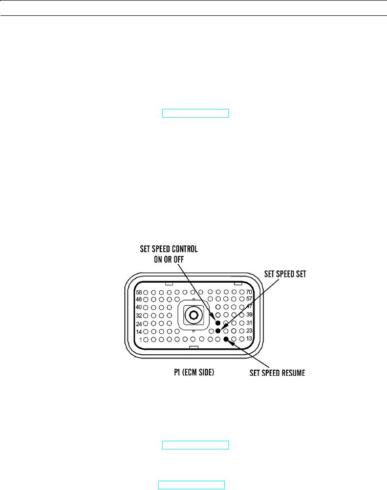
Measure resistance between P1:11 Set Speed Control Resume and P1:68 -battery. First measure resistance with
switch in OFF position and then measure switch in ON position.
e.
Measure resistance between P1:68 and each of these ECM pin locations:
(1)
P1:20 Set Speed Control Set
(2)
P1:28 Set Speed Control ON or OFF
f.
Expected Results. Measured resistance should be less than 10 Ohms with switch in ON position. Measured resis-
tance should be more than 2,000 Ohms with switch in OFF position.
427-B0911
(1)
If results are OK, proceed to step 7.
(2)
If results are NOT OK, a problem exists in wires between MIC and ECM connector. Replace wiring har-
ness in question (WP 0169 00 thru WP 0175 00). Verify repair has eliminated problem. If problem has not
been eliminated, repeat Electrical Connectors Inspection (WP 0022 00).
6.
Test engine ECM.
a.
Turn engine start switch to OFF position (TM 5-3805-290-10).
b.
Insert 70-pin breakout T between P1 connector and J1 connector.
c.
Insert one end of jumper wire into socket for suspect switch. Insert other end of jumper wire into P1:68 -battery.
d.
Turn engine start switch to ON position (TM 5-3805-290-10) and monitor status screen on MSD. Slowly connect
and disconnect jumper wire from socket of pin 68 of breakout T.
0013 00-66

