
TM 5-3805-290-23-1
ELECTRICAL SYSTEM TESTS, INSPECTIONS, AND ADJUSTMENTS - CONTINUED
0013 00
SET SPEED CIRCUIT TEST - CONTINUED
3.
Check speed control switch.
a.
Turn engine start switch to OFF position (TM 5-3805-290-10).
b.
Remove wire from MIC P20:11 set speed control Resume switch. Use jumper to join P20:11 together with each
wire listed below.
c.
Turn engine start switch to ON position (TM 5-3805-290-10).
d.
Monitor status screen on MSD. Slowly connect and disconnect jumper from P20:11.
(1)
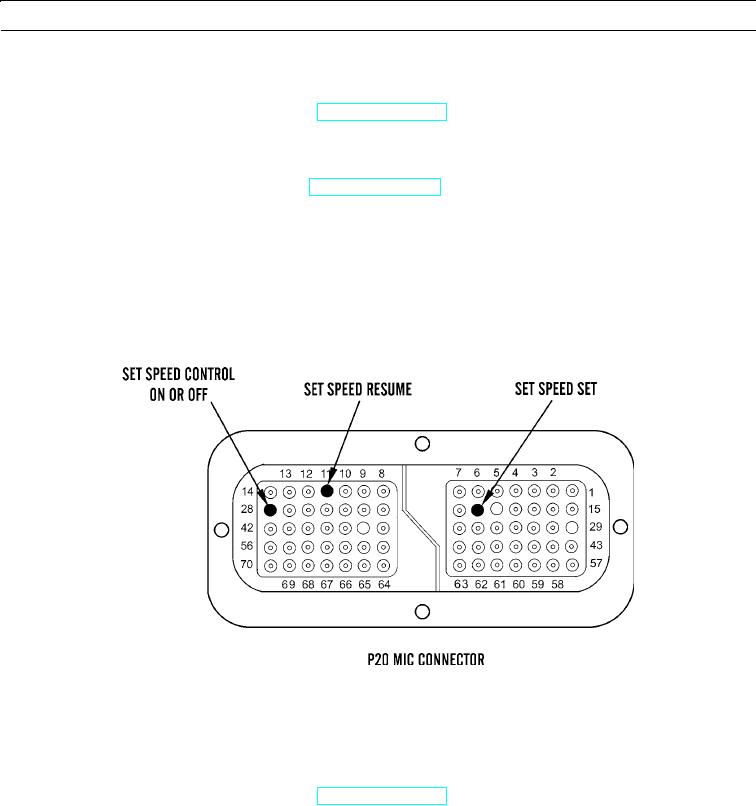
P20:20 Set Speed Control Set
(2)
P20:28 Set Speed Control ON or OFF
e.
Expected Results. When jumper wire is connected, set speed switch should be CLOSED. When jumper wire is dis-
connected, set speed switch should be OPEN.
427-B0912
(1)
If results are OK, switch is faulty. Replace switch (WP 0049 00) and verify repair has eliminated problem.
(2)
If results are NOT OK, a problem exists with wiring harness between set speed control switch and engine
ECM. Proceed to step 5.
4.
Measure resistance of cables at MIC.
a.
Turn engine start switch to OFF position (TM 5-3805-290-10).
b.
Connect meter to suspect switch.
c.
Disconnect P20:11 Set Speed Control Resume switch from P20/J20 MIC.
d.
Measure resistance from P20:11 Set Speed Control Resume switch to P20:68 -battery.
e.
Measure resistance between P20:68 -battery and each of these connections:
(1)
P20:20 Set Speed Control Set
(2)
P20:28 Set Speed Control ON or OFF
0013 00-65