TM 5-3805-290-23-1
BRAKE SYSTEM TESTS, INSPECTIONS, AND ADJUSTMENTS - CONTINUED
0015 00
SERVICE BRAKE DISCS WEAR CHECK - CONTINUED
N OT E
The following steps require accumulator pressure.
4.
With assistance, hold down either brake pedal. This will hold piston, brake disc, and plate together.
N OT E
Light and mirror are needed to view brake discs through ports.
5.
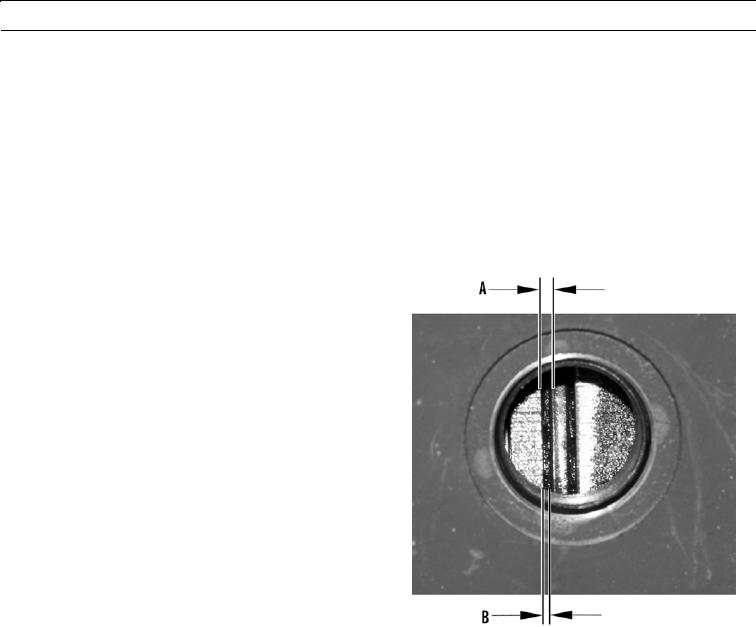
Use feeler gage to measure thickness of brake disc
(Dimension A). Minimum thickness should be
between 0.250 and 0.307 in. (6.35 and 7.8 mm) (front
brakes).
Insert brake wear gage between reaction plates while
6.
brakes are applied. Tool is go/no-go gage. If tool fits
between reaction plates, thickness of brake disc is
acceptable. If tool does not fit between reaction plates,
thickness of brake disc is not acceptable and brake
discs need to be replaced (rear brakes).
427-B0948
CAU T I ON
Oil groove depth is the most critical dimension. If depth of oil grooves on friction discs are too shallow, oil
flow will be inadequate. This can cause excessive heat and abrasion.
7.
Use a wire feeler gage to measure width of oil grooves (Dimension B) on both sides of friction discs in each axle hous-
ing. Depth of oil grooves cannot be less than 0.041 in. (1.05 mm).
N OT E
If one or more brake discs do not comply with minimum specifications, replace axle (WP 0179 00 or WP
0180 00) before returning machine to service.
8.
Install inspection plugs.
END OF WORK PACKAGE
0015 00-5/(0015 00-6 Blank)

