
TM 5-3805-290-23-1
STEERING SYSTEM TESTS, INSPECTIONS, AND ADJUSTMENTS - CONTINUED
0016 00
16
WARN I N G
When servicing this machine, performing maintenance, or disposing of hazardous materials, consult your
unit/local hazardous waste disposal center or safety office for local regulatory guidance. If further informa-
tion is needed, please contact The Army Environmental Hotline at 1-800-872-3845.
DO NOT disconnect or remove any hydraulic system lines or fitting unless engine is shut down and hydraulic
system pressure has been relieved. Tighten all connections before applying pressure. Escaping hydraulic fluid
under pressure can penetrate the skin, causing injury to personnel.
At operating temperature, hydraulic oil is hot. Allow hydraulic oil to cool before removing any hydraulic fit-
ting. Failure to follow this warning may result in injury to personnel.
To prevent injury to personnel, wear protective eye covering and gloves.
Sudden movement of machine can cause injury to personnel on or near the machine.
16
16
N OT E
For a better understanding of each system, review the appropriate section in Theory of Operation (WP 0003
0016 00
PISTON PUMP (STEERING AND PILOT) LOW PRESSURE STANDBY TEST AND ADJUSTMENT
1.
To release any steering system pressure, turn steering
wheel to left and right.
2.
Remove chassis cover from right side of machine (WP
0107 00).
3.
Connect Coupling, hose (Item 26, WP 0205 00) to end
of Hose (Item 38, WP 0205 00).
4.
Connect Nipple, pipe (Item 49, WP 0205 00) to other
end of hose Hose (Item 38, WP 0205 00).
5.
Install Coupling, hose (Item 27, WP 0205 00) on pres-
sure gage.
6.
Connect Nipple, pipe (Item 49, WP 0205 00) onto one
end of hose to pressure gage.
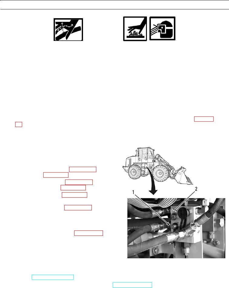
7.
Remove cap from pressure tap (1) of reducing valve
(2).
8.
Connect Coupling, hose (Item 27, WP 0205 00) on
hose to pressure tap (1) on pressure reducing valve (2).
427-B0949
9.
Start engine (TM 5-3805-290-10).
10.
Run engine at high idle. DO NOT move steering wheel (TM 5-3805-290-10).
11.
Expected Results. Pressure should be 590 30 psi (4,065 205 kPa).