
TM 5-3805-290-23-2
THROTTLE PEDAL AND THROTTLE POSITION SENSOR REPLACEMENT - CONTINUED
0039 00
THROTTLE PEDAL REMOVAL - CONTINUED
3.
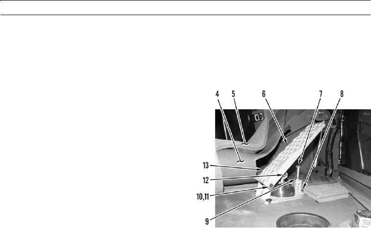
Inside cab, lift floor mat (4) and foam pad (5) away from throttle pedal (6). Set floor mat and foam pad aside.
N OT E
Perform step 4 if new throttle pedal is to be installed. Measurement will be transferred to new throttle
pedal.
4.
Measure and record distance between top of adjust-
ment screw (7) and raised area at base of throttle pedal
(6). Measurement will be approximately 1 1/2 in. (38
mm).
5.
Remove three screws (8) and throttle pedal (6) from
floor of machine.
6.
Remove two clips (10 and 11), pin (12), and pedal
(13) from pedal assembly (6).
427-B1206
THROTTLE PEDAL INSTALLATION
1.
Install pedal (13), pin (12), and two clips (10 and 11) on pedal assembly (6).
N OT E
Perform step 2 if new throttle pedal is to be installed.
2.
Ensure adjustment screw (7) measurement is same as taken in Throttle Pedal Removal in this work package. If not,
loosen nut (9) and adjust screw as necessary. Tighten nut to 11 2 lb-ft (15 3 Nm).
N OT E
Ensure sensor is oriented same as it was prior to removal to ensure sensor harness pigtail is routed cor-
rectly.
3.
Install throttle pedal (6) on floor of machine with three screws (8).
4.
Position foam pad (5) and floor mat (4) on floor of cab and around throttle pedal (6).
0039 00-2