
TM 5-3805-290-23-2
CONTROL SWITCHES AND PANELS REPLACEMENT - CONTINUED
0049 00
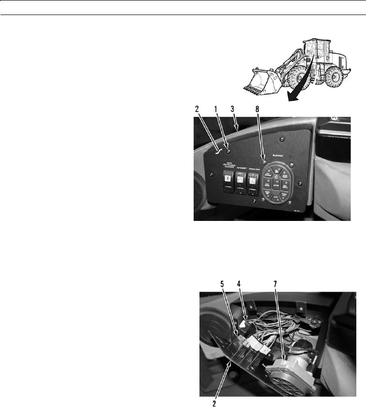
LEFT-SIDE CONTROL PANEL AND SWITCHES REMOVAL
0049 00
1.
Remove five screws (1) from instrument panel cover
(2).
CAU T I ON
Take care to ensure wiring is not damaged
while performing this procedure.
N OT E
Tag wires prior to removal to ensure cor-
rect installation.
2.
Pull instrument panel cover (2) away from dash (3).
427-B0881
N OT E
Squeeze side tabs to release toggle switch from cover.
3.
Disconnect three wiring harness connectors (4) from
toggle switches (5).
4.
Disconnect cannon plug (6) from military light switch
(7).
5.
Remove four screws (8) and military light switch (7)
from instrument panel cover (2).
6.
Remove three toggle switches (5) from instrument
panel cover (2).
427-B0883
0049 00-2