
TM 5-3805-290-23-2
CONTROL SWITCHES AND PANELS REPLACEMENT - CONTINUED
0049 00
LEFT-SIDE CONTROL PANEL AND SWITCHES REMOVAL - CONTINUED
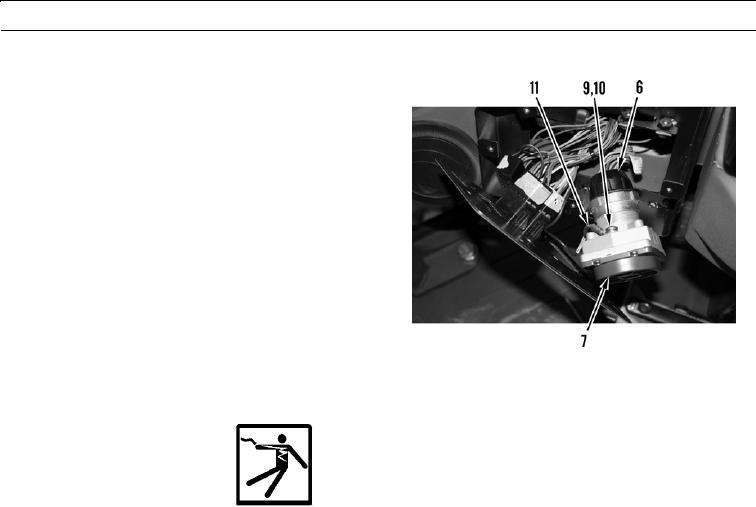
7.
Remove screw (9), lockwasher (10), and ground cable
(11) from military light switch (7). Discard lock-
washer.
427-B0884
LEFT-SIDE CONTROL PANEL AND SWITCHES INSTALLATION
WARN I N G
Ensure battery disconnect switch is in OFF position before performing this task. Failure to follow this
warning may result in injury to personnel or damage to equipment.
CAU T I ON
Take care to ensure wiring is not damaged when performing this procedure.
1.
Install ground cable (11), new lockwasher (10), and screw (9) on military light switch (7).
2.
Connect cannon plug (6) to military light switch (7).
3.
Install three toggle switches (5) on instrument panel cover (2).
4.
Install three wiring harness connectors (4) on toggle switches (5).
5.
Position military light switch (7) in instrument panel cover (2).
6.
Install four screws (8) in military light switch (7).
7.
Position instrument panel cover (2) in dash (3) and install five screws (1) in instrument panel cover.
0049 00-3