
TM 5-3805-290-23-2
DRIVE SHAFT MAINTENANCE - CONTINUED
0090 00
CENTER DRIVE SHAFT INSTALLATION - CONTINUED
WAR N I N G
Before operating equipment, secure the steering frame lock in the stowed position. DO NOT operate
machine with steering frame lock connected. Failure to lock steering frame lock into the stowed position
before operating can result in loss of steering and injury or death to personnel.
3.
Secure steering frame lock in stowed position (TM 5-3805-290-10).
4.
Operate machine at different speeds to verify correct operation (TM 5-3805-290-10).
FRONT DRIVE SHAFT REMOVAL
N OT E
Front drive shaft is on a slip yoke.
Match mark shaft and yoke to
ensure correct installation.
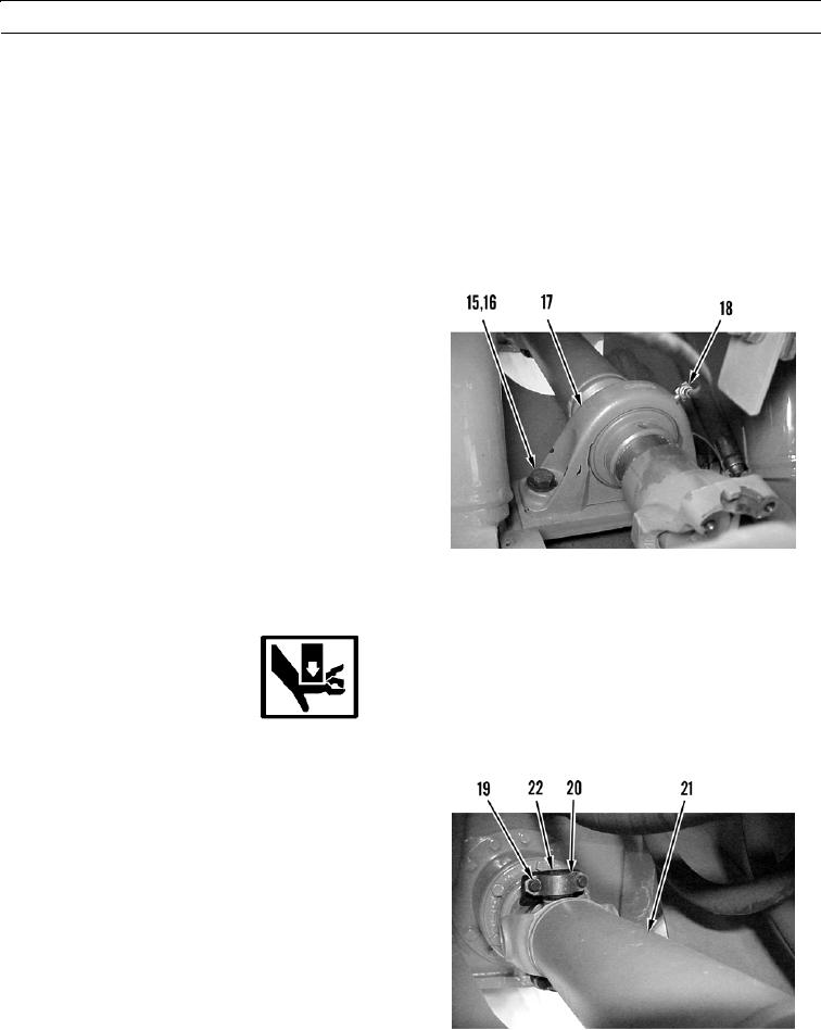
1.
Remove two bolts (15) and washers (16) from bearing
(17).
2.
Disconnect hose assembly (18) from bearing (17).
427-B0029
WARN I N G
Use extreme caution when handling heavy parts. Provide adequate support and use assistance during pro-
cedure. Failure to follow this warning may result in injury to personnel.
N OT E
Front drive shaft assembly weighs 42 lb (19.4 kg).
3.
With assistance, remove four bolts (19), two straps
(20), and front drive shaft assembly (21) from yoke
(22).
427-B0030
0090 00-6