
TM 5-3805-290-23-2
PARKING BRAKE MAINTENANCE - CONTINUED
0092 00
LIMIT SWITCH REMOVAL
1.
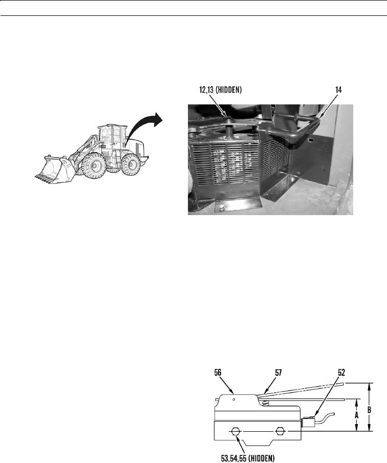
Remove three bolts (12), washers (13), and handle (14).
2.
Disconnect wiring harness (52).
3.
Remove two nuts (53), bolts (54), washers (55), and limit switch (56).
427-B1958F
LIMIT SWITCH INSTALLATION
1.
Loosely install limit switch (56), two washers (55), bolts (54), and nuts (53).
2.
Adjust limit switch and tighten nuts (53). Refer to Limit Switch Adjustment in this work package.
3.
Connect wiring harness (52).
4.
Verify correct operation of limit switch (TM 5-3805-290-10).
5.
Install handle (14), three washers (13), and bolts (12).
LIMIT SWITCH ADJUSTMENT
N OT E
Adjust limit switch with brake handle assembly at lowest position. The adjustment for the limit switch is
made at mounting location for limit switch.
Adjust limit switch (56) so actuator (57) is pressed
0.080 0.003 in. (2 0.8 mm) to operating position (A)
from free movement position (B).
427-B0035-1
END OF WORK PACKAGE
0092 00-12