
TM 5-3805-290-23-2
PARKING BRAKE MAINTENANCE - CONTINUED
0092 00
INSTALLATION - CONTINUED
27.
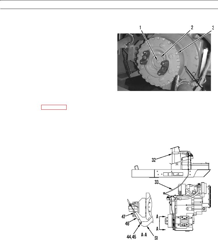
Install retainer (2) and bolt (1) on brake drum (3).
Tighten bolt to 90 15 lb-ft (120 20 Nm).
427-B0014
28.
Install drive shaft (WP 0090 00).
CABLE ADJUSTMENT
N OT E
The following procedure is used to adjust the amount of play in the linkage of the parking brake control.
1.
Move parking brake lever to DISENGAGED position.
2.
Loosen nut (47). Remove cotter pin (44). Remove cle-
vis pin (45) from clevis (46).
3.
Pull down on clevis (46) to remove slack from brake
handle assembly (32) and from parking brake cable
(33).
4.
Push up on lever assembly (51) to remove slack from
brake.
5.
Turn clevis (46) to align hole in lever assembly (51)
with hole in clevis.
6.
Turn clevis (46) down two turns to allow free play in
brake handle assembly (32).
7.
Install clevis pin (45) and cotter pin (44) on machine.
427-B0015-1
8.
Tighten nut (47) to 20 5 lb-ft (28 7 Nm).
N OT E
Brake handle assembly should not reach end of stroke when parking brake is fully engaged.
9.
Check adjustment. Parking brake is adjusted correctly when there is 0.9 0.1 in. (22.5 2.5 mm) of free play at end of
brake handle assembly (32).
0092 00-11