
6
TM 5-3805-290-23-2
BRAKE PEDALS AND STOPLAMP SWITCH REPLACEMENT
THIS WORK PACKAGE COVERS
Brake Pedals: Removal, Cleaning and Inspection, Installation, Adjustment
Stoplamp Switch: Removal, Installation, Adjustment
INITIAL SETUP
Personnel Required
Maintenance Level
Unit
MOS 62B, Construction Equipment Repairer
Tools and Special Tools
Equipment Conditions
Tool kit, general mechanic's (Item 96, WP 0205 00)
Steering column removed (WP 0099 00)
Materials/Parts
Drawings Required
Cleaning compound, solvent, type III (Item 9, WP
TM 5-3805-290-23P, Figure 83
Estimated Time to Complete Task
Rag, wiping (Item 41, WP 0206 00)
1.0 hr brake pedals
Bearing (4)
0.2 hr stoplamp switch
Cotter pin
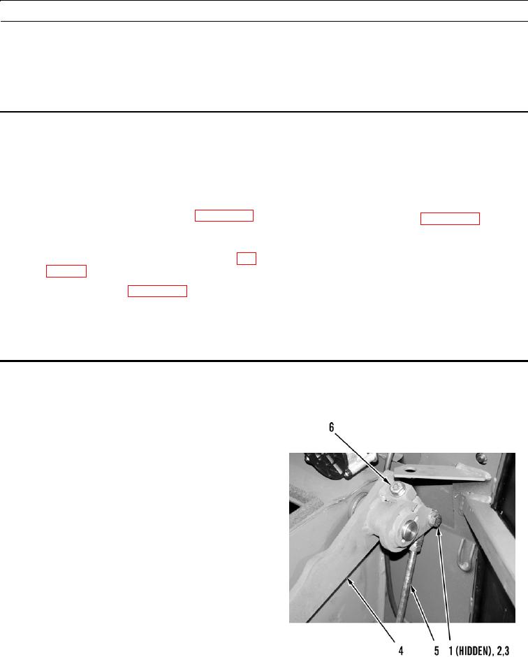
BRAKE PEDALS REMOVAL
1.
Remove cotter pin (1), retaining pin (2), and washer
(3) from RH brake pedal (4) and linkage rod (5). Dis-
card cotter pin.
2.
Loosen retaining bolt (6) and remove RH brake pedal
(4) from machine.
427-B1111