
TM 5-3805-290-23-2
SERVICE BRAKE CONTROL VALVE REPLACEMENT - CONTINUED
0093 00
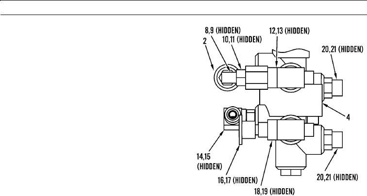
COMPONENT TRANSFER
1.
Remove pressure sensor (2), elbow (8), and two O-
rings (9) from service brake control valve (4). Discard
O-rings.
2.
Remove fitting (10) and O-ring (11) from service
brake control valve (4). Discard O-ring.
3.
Remove T (12) and O-ring (13) from service brake
control valve (4). Discard O-ring.
4.
Remove elbow (14) and O-ring (15) from service
brake control valve (4). Discard O-ring.
5.
Remove fitting (16) and O-ring (17) from service
brake control valve (4). Discard O-ring.
6.
Remove T (18) and O-ring (19) from service brake
control valve (4). Discard O-ring.
7.
Remove two connectors (20) and O-rings (21) from
service brake control valve (4). Discard O-rings.
427-B0024-6
N OT E
Apply a thin coat of clean oil to all O-rings
prior to installation.
8.
Install two new O-rings (21) and connectors (20) on
service brake control valve (4).
9.
Install new O-ring (19) and T (18) on service brake control valve (4).
10.
Install new O-ring (17) and fitting (16) on service brake control valve (4).
11.
Install new O-ring (15) and elbow (14) on service brake control valve (4).
12.
Install new O-ring (13) and T (12) on service brake control valve (4).
13.
Install new O-ring (11) and fitting (10) on service brake control valve (4).
14.
Install two new O-rings (9), elbow (8), and pressure sensor (2) on service brake control valve (4).
INSTALLATION
1.
Position service brake control valve (4) under operator cab and install two washers (7) and bolts (6) in service brake
control valve. Tighten bolts to 40 7 lb-ft (54 9 Nm).
2.
Lubricate and install five new O-rings (5) and connect hoses (3) to service brake control valve (4).
3.
Connect wiring harness (1) to pressure sensor (2).
0093 00-3