
TM 5-3805-290-23-2
MAIN CONTROL VALVE HOSES, LINES, AND FITTINGS REPLACEMENT - CONTINUED
0134 00
C AU T I O N
Wipe area clean around all connections to be opened during removal. Cap lines and hoses and plug open-
ings after removing lines. Contamination of system could result in premature failure.
N OT E
Tag hoses prior to removal to ensure correct installation.
Use a container to catch any fluid that may drain from hoses or system. Dispose of fluid IAW local pol-
icy and ordinances. Ensure all spills are cleaned up.
REMOVAL
1.
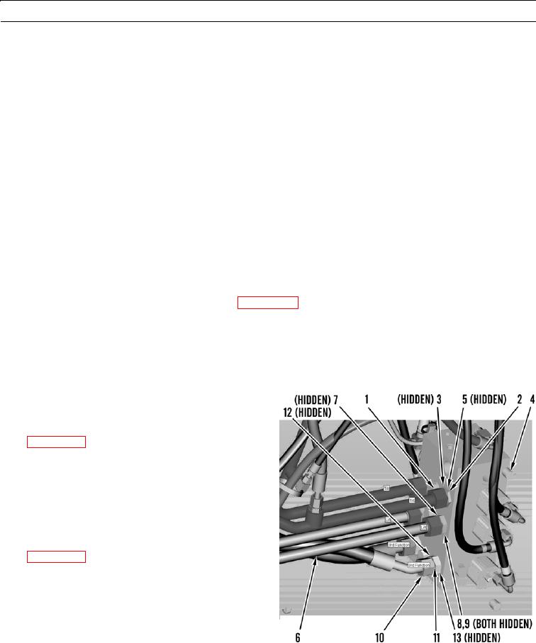
Disconnect hose (1) from fitting (2).
2.
Remove and discard O-ring (3).
3.
Remove fitting (2) from main control valve (4).
4.
Remove and discard O-ring (5).
5.
Remove hose (1) and fitting from tilt cylinder line (WP 0131 00) and remove hose from machine.
6.
Repeat steps 1 thru 5 for tilt hose on other side.
7.
Disconnect hose (6) from fitting (7).
8.
Remove and discard O-ring (8).
9.
Remove fitting (7) from main control valve (4).
10.
Remove and discard O-ring (9).
11.
Remove hose (6) and fitting from lift cylinder line
(WP 0131 00) and remove hose from machine.
12.
Repeat steps 7 thru 11 for lift hose on other side.
13.
Disconnect hose (10) from fitting (11).
14.
Remove and discard O-ring (12).
15.
Remove fitting (11) from main control valve (4).
16.
Remove and discard O-ring (13).
17.
Remove hose (10) and fitting from third function line
(WP 0131 00) and remove hose from machine.
18.
Repeat steps 13 thru 17 for third function hose on
other side.
427-B1821
0134 00-2