
TM 5-3805-290-23-2
MAIN CONTROL VALVE HOSES, LINES, AND FITTINGS REPLACEMENT - CONTINUED
0134 00
REMOVAL - CONTINUED
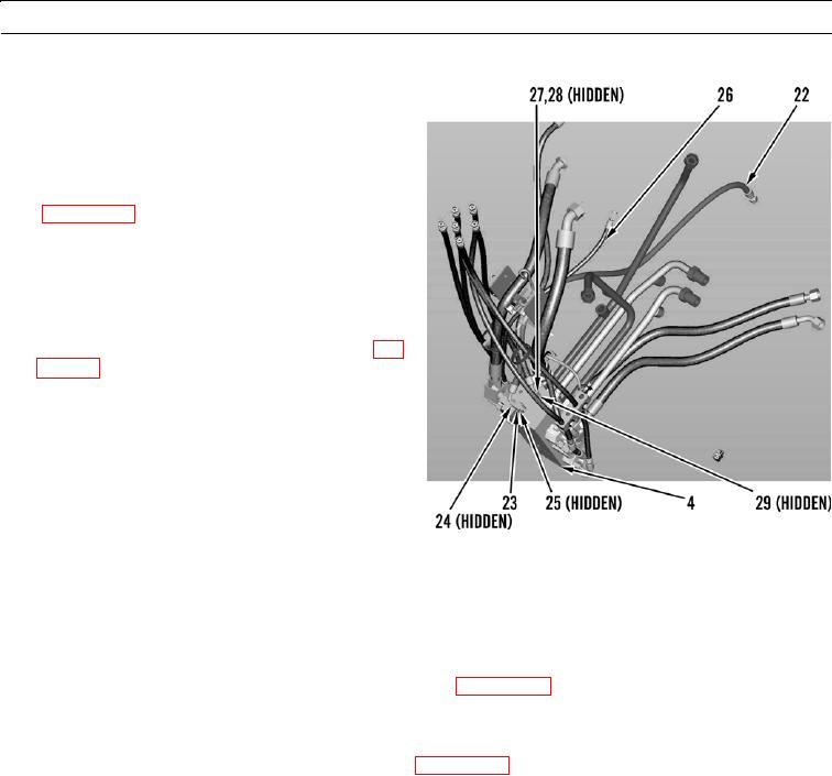
29.
Disconnect hose (22) from fitting (23).
30.
Remove and discard O-ring (24).
31.
Remove fitting (23) from main control valve (4).
32.
Remove and discard O-ring (25).
33.
Remove hose (22) and fitting from ride control valve
(WP 0133 00) and remove hose from machine.
34.
Disconnect hose (26) from fitting (27).
Remove and discard O-ring (28).
35.
36.
Remove fitting (27) from main control valve (4).
37.
Remove and discard O-ring (29).
38.
Remove hose (26) from pressure reducing valve (WP
0125 00) and remove hose from machine.
427-B1821
427-B1803
INSTALLATION
N OT E
Apply a thin coat of clean oil to all O-rings before installation.
1.
Install fitting and connect hose (26) to pressure reducing valve (WP 0125 00).
2.
Install new O-ring (29) and fitting (27) on main control valve (4).
3.
Install new O-ring (28) and connect hose (26) to fitting (27).
4.
Install fitting and connect hose (22) to ride control valve (WP 0133 00).
5.
Install new O-ring (25) and fitting (23) on main control valve (4).
6.
Install new O-ring (24) and connect hose (22) to fitting (23).
0134 00-4