
TM 5-3805-290-23-2
TIMING AND IDLER GEARS REPLACEMENT - CONTINUED
0153 00
CLEANING AND INSPECTION - CONTINUED
N OT E
If one or more of the gears need to be removed for repair, refer to Removal in this work package.
Refer to Specifications in this work package for correct tolerances.
3.
Inspect the gears for wear or for damage. If the gears are worn or damaged, use new parts for replacement.
4.
Measure the backlash on camshaft gear.
5.
Measure the backlash on idler gear.
6.
Measure the backlash on fuel injection pump gear.
7.
Measure the end play on idler gear.
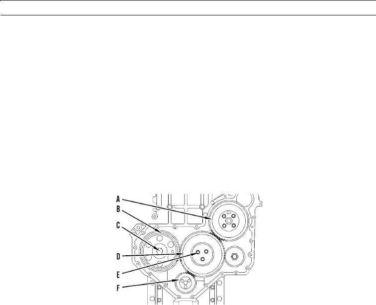
Specifications
427-B2064
A. Fuel injection pump gear:
Bore: 1.417 to 1.420 in. (36.00 to 36.06 mm).
Tighten four bolts to 21 lb-ft (28 Nm).
N OT E
The crankshaft must not be turned unless the fuel injection pump gear is installed.
Do not remove the nut that retains the hub of the fuel injection pump to the shaft of the fuel injection
pump. If the hub is removed, the hub must be positioned by correctly trained personnel and special test
equipment.
B. Camshaft gear:
Bore diameter of camshaft gear: 1.3752 to 1.3760 in. (34.930 to 34.950 mm).
Outside diameter of camshaft hub: 1.3741 to 1.3747 in. (34.900 to 34.920 mm).
Clearance between the camshaft gear and camshaft hub: 0.0003 to 0.0019 in. (0.008 to 0.048 mm).
C. Tighten bolt for camshaft gear to 70 lb-ft (95 Nm).
0153 00-5