
TM 5-3805-290-23-2
TIMING AND IDLER GEARS REPLACEMENT - CONTINUED
0153 00
INSTALLATION - CONTINUED
WARN I N G
Hot oil or metal parts can cause severe burns. Wear insulated gloves, long sleeves, and eye protection
when working with heated parts. Failure to follow this warning may result in injury to personnel.
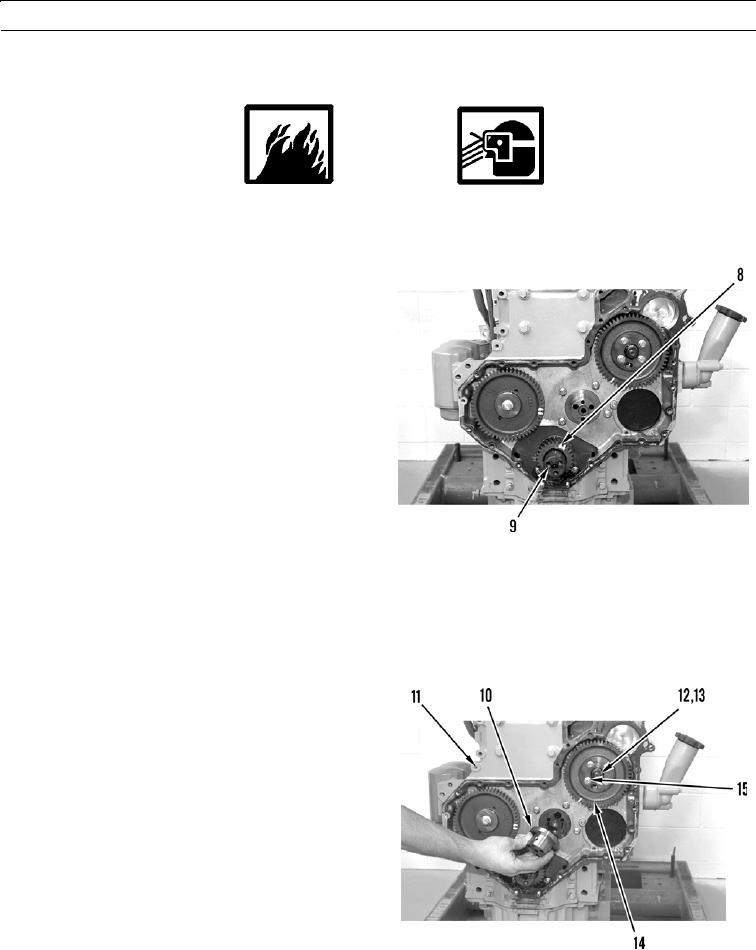
5.
Heat crankshaft gear (8) to 356F (180C).
N OT E
Ensure timing marks on crankshaft
gear and idler gear are aligned.
6.
Install crankshaft gear (8) on crankshaft (9) with tim-
ing marks toward front.
427-B0507
7.
Install fuel injection pump gear (14) on cylinder block (11).
8.
Install four bolts (15) on fuel injection pump gear (14). Tighten bolts to 21 lb-ft (28 Nm).
9.
Install spring washer (13) and nut (12) on fuel injection pump gear (14). Tighten nut to 59 lb-ft (80 Nm).
N OT E
Machine bores for clearance on idler
gear hub to 0.0016 to 0.0039 in. (0.041 to
0.099 mm). Bore can have a diameter of
2.250 to 2.251 in. (57.15 to 57.18 mm).
10.
Install idler gear hub (10) on cylinder block (11).
427-B0503
0153 00-8