
TM 5-3805-290-23-2
TIMING AND IDLER GEARS REPLACEMENT - CONTINUED
0153 00
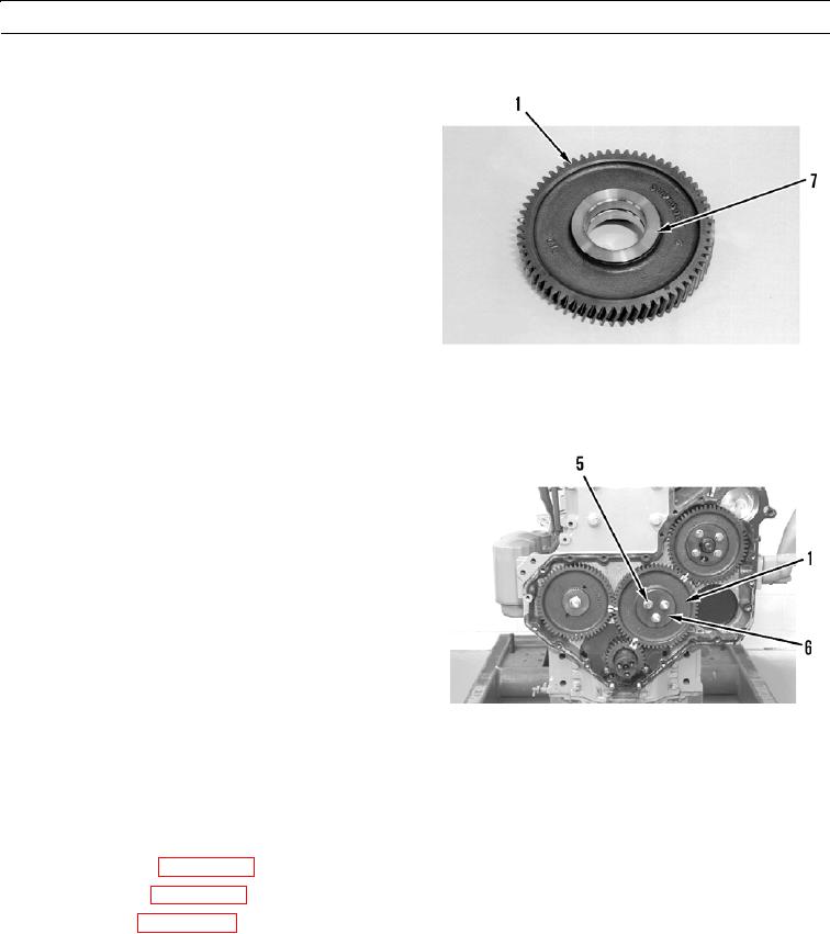
INSTALLATION - CONTINUED
11.
Use press to install two new bushings (7) on idler gear
(1) if removed.
427-B0502
12.
Install retainer plate (6) on idler gear (1).
N OT E
Ensure that timing marks on crankshaft
gear, camshaft gear, and idler gear are
aligned.
13.
Install three bolts (5) on idler gear (1). Tighten bolts to
32 lb-ft (44 Nm).
427-B0500
14.
Position dial indicator to measure end play and set dial indicator to 0.00 in. (0.00 mm). Minimum backlash for new gear
is 0.004 to 0.008 in. (0.10 to 0.20 mm).
15.
Position dial indicator to measure backlash and set dial indicator to 0.00 in. (0.00 mm). Minimum backlash between
camshaft gear and idler gear must be 0.003 in. (0.08 mm).
16.
Install front cover (WP 0152 00).
17.
Install fan group (WP 0168 00).
18.
Check oil level (WP 0025 00).
19.
Run engine until correct operating temperature is reached (TM 5-3805-290-10).
20.
Shut engine down (TM 5-3805-290-10).
21.
Check for leaks.
END OF WORK PACKAGE
0153 00-9/(0153 00-10 Blank)