TM 5-3805-290-23-2
INTAKE/EXHAUST VALVE LASH ADJUSTMENT - CONTINUED
0155 00
INSPECTION/ADJUSTMENT - CONTINUED
9.
Measure valve lash when engine is at TC compression stroke according to Table 1. If necessary, make an adjustment to
valves according to Table 1.
a.
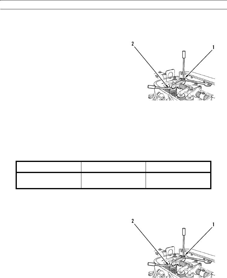
Loosen valve adjustment screw locknut on
adjustment screw (1).
b.
Place appropriate feeler gage (2) between rocker
arm and valve. Turn adjustment screw (1) while
valve adjustment screw locknut is being held.
Adjust valve lash until correct specification is
achieved.
c.
After each adjustment, tighten valve adjustment
screw locknut while holding valve adjustment
screw (1) from turning.
427-B0511
N OT E
A mark on the vibration damper pulley may be used as a point of reference when rotating engine.
10.
Rotate crankshaft direction of engine rotation to TC exhaust stroke (360 from TC compression stroke) (WP 0002 00).
Table 2.
TC EXHAUST STROKE(1)
INLET VALVES
EXHAUST VALVES
Valve Lash
0.008 in. (0.20 mm)
0.018 in. (0.45 mm)
Cylinders
3-5-6
2-4-6
(1)
360 from TC compression stroke.
11.
Measure valve lash when engine is at TC exhaust stroke according to Table 2. If necessary, make adjustment to valves
according to Table 2.
a.
Loosen valve adjustment screw locknut on
adjustment screw (1).
b.
Place appropriate feeler gage (2) between rocker
arm and valve. Turn adjustment screw (1) while
valve adjustment screw locknut is being held.
Adjust valve lash until correct specification is
achieved.
c.
After each adjustment, tighten valve adjustment
screw locknut while holding valve adjustment
screw (1) from turning.
427-B0511
0155 00-3

