
TM 5-3805-290-23-2
TURBOCHARGER AND OIL LINES REPLACEMENT - CONTINUED
0165 00
INSPECTION - CONTINUED
Wastegate Inspection
N OT E
The wastegate controls the amount of exhaust gas that is allowed to bypass the turbine side of the turbo-
charger. This valve then controls the rpm of the turbocharger.
When the engine operates in conditions of low boost (lug), a spring presses against a diaphragm in the
canister. The actuating rod will move and the wastegate will close. Then, the turbocharger can operate at
maximum performance.
When the boost pressure increases against the diaphragm in the canister, the wastegate will open. The
rpm of the turbocharger becomes limited. The rpm limitation occurs because a portion of the exhaust
gases bypass the turbine wheel of the turbocharger.
The following levels of boost pressure indicate a problem with the wastegate:
a.
Too high at full load conditions.
b.
Too low at all lug conditions.
Boost pressure is 20.45 0.4 psi (141 3 kPa).
The boost pressure controls the maximum rpm of the turbocharger, because the boost pressure controls
the position of the wastegate. The following factors also affect the maximum rpm of the turbocharger:
a.
Engine rating.
b.
Horsepower demand on the engine.
c.
High idle rpm.
d.
Inlet air restriction.
e.
Exhaust system restriction.
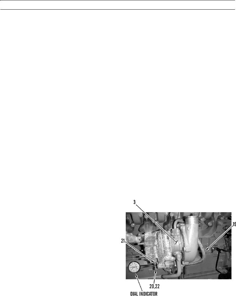
1.
Disconnect boost line (19) from turbocharger (3).
Connect an air supply to line that can be adjusted
accurately.
2.
Fasten dial indicator to turbocharger (3) so that end of
actuator rod (20) contacts dial indicator. This will
measure axial movement of actuator rod. Ensure that
cotter pin (22) is secure.
3.
Slowly apply air pressure to boost line (19) until actu-
ator rod (20) moves 0.039 in. (1.0 mm). Air pressure
should be from 15.5 to 17 psi (107 to 117 kPa). Ensure
dial indicator returns to zero when air pressure is
released. Repeat test several times to ensure an accu-
427-B0092-1
rate reading is obtained.
4.
If air pressure is not as specified in step 3, go to Waste-
gate Adjustment in this work package.
0165 00-7