
TM 5-3805-290-23-2
REAR TILT LEVER AND LINK REPLACEMENT - CONTINUED
0200 00
TILT LEVER INSTALLATION - CONTINUED
3.
Apply grease to pin bores and lip seals.
WARN I N G
Use extreme caution when handling heavy parts. Provide adequate support and use assistance during
procedure. Ensure any lifting equipment used is in good condition and of suitable load capacity. Keep
clear of heavy parts supported only by lifting equipment. Failure to follow this warning may result in
injury or death to personnel.
N OT E
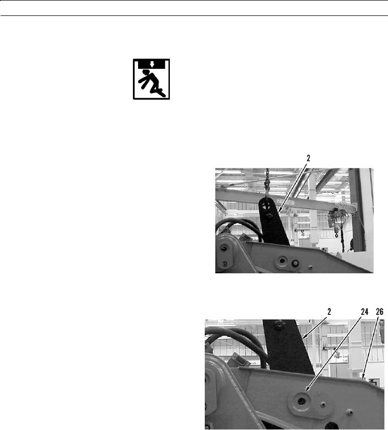
Rear lever assembly weighs 225 lb
(102 kg).
Pin assembly weighs 90 lb (41 kg).
4.
Use lifting equipment to support rear lever assembly
(2).
427-B0977
5.
With assistance, install pin assembly (24) to secure
rear lever assembly (2) to arm (26).
427-B0643
0200 00-9