
TM 5-3805-290-23-2
REAR TILT LEVER AND LINK REPLACEMENT - CONTINUED
0200 00
TILT LEVER INSTALLATION - CONTINUED
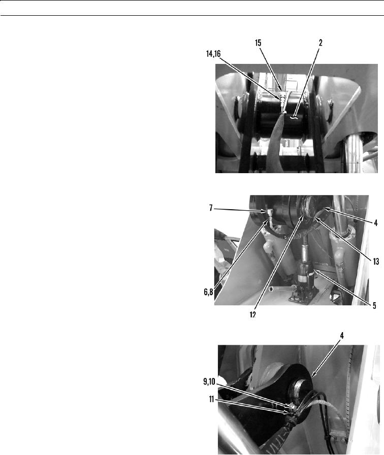
10.
Install new O-ring (16) in grease line (14). Connect
grease line to fitting (15) on rear lever assembly (2).
427-B0639
11.
Install new O-ring (8) in grease line (6). Connect
grease line to fitting (7) on rear link assembly (4).
427-B0638
12.
Install washer (10) and bolt (9) in clamp (11) on link
assembly (4).
13.
Install retaining ring (12) on pin assembly (13).
427-B0980
0200 00-11