
TM 5-3805-290-23-2
REAR TILT LEVER AND LINK REPLACEMENT - CONTINUED
0200 00
TILT LINK REMOVAL
1.
Support boom with jack stand (3).
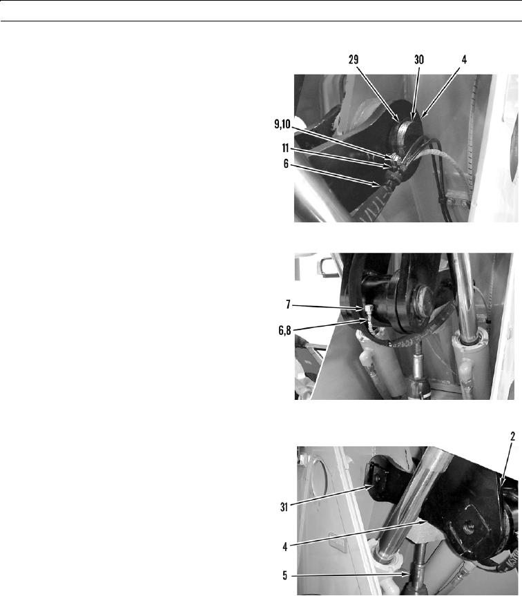
2.
Remove bolt (9) and washer (10) from clamp (11) on
rear link assembly (4). Position grease lines (6) aside.
3.
Remove retaining ring (29) from pin (30).
427-B0981
4.
Disconnect grease line (6) from fitting (7). Remove O-
ring (8) from grease line and discard.
427-B0982
5.
Use hydraulic jack (5) and wood block to support rear
link assembly (4).
6.
Remove pin assembly (31) from rear link assembly
(4).
7.
Lower rear link assembly (4) from rear lever assembly
(2).
427-B0983
0200 00-13