
TM 5-3805-290-23-2
REAR TILT LEVER AND LINK REPLACEMENT - CONTINUED
0200 00
TILT LINK INSTALLATION - CONTINUED
13.
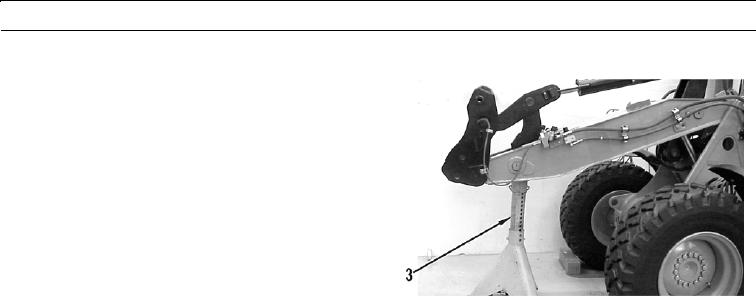
Remove jack stand (3) and lower boom.
427-B0637
WAR N I N G
Before operating equipment, secure the steering frame lock in the stowed position. DO NOT operate
machine with steering frame lock connected. Failure to lock steering frame lock into the stowed posi-
tion before operating can result in loss of steering and injury or death to personnel.
14.
Secure steering frame lock in stowed position (TM 5-3805-290-10).
15.
Check hydraulic level (TM 5-3805-290-10).
16.
Run engine until normal operating temperature is reached (TM 5-3805-290-10).
17.
Shut down engine (TM 5-3805-290-10).
18.
Check for leaks.
END OF WORK PACKAGE
0200 00-17/(0200 00-18 Blank)