
TM 5-3805-290-23-2
REAR TILT LEVER AND LINK REPLACEMENT - CONTINUED
0200 00
TILT LINK INSTALLATION - CONTINUED
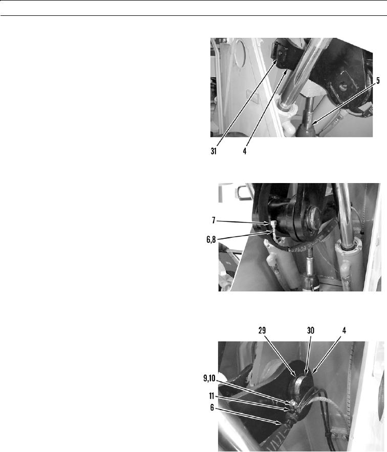
7.
Use hydraulic jack (5) and wood block to support rear
link assembly (4).
8.
Install pin assembly (31) through rear link assembly
(4).
9.
Remove hydraulic jack (5) and wood block.
427-B0987
10.
Install new O-ring (8) in grease line (6). Connect
grease line to fitting (7).
427-B0982
11.
Install retaining ring (29) on pin (30).
12.
Position grease line (6) on rear link assembly (4).
Install washer (10) and bolt (9) in clamp (11).
427-B0981
0200 00-16