
TM 5-3805-290-23-2
REAR TILT LEVER AND LINK REPLACEMENT - CONTINUED
0200 00
TILT LINK REMOVAL - CONTINUED
13.
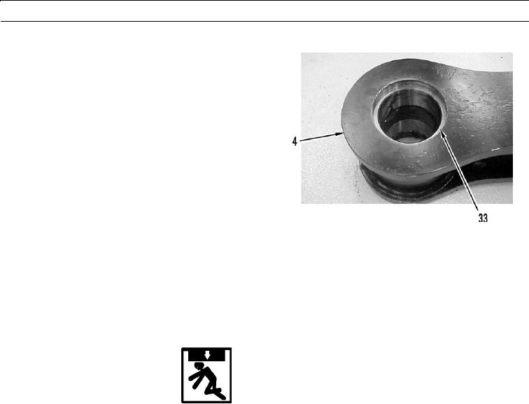
Remove bearing sleeve (33) from rear link assembly
(4). Repeat for opposite side of bore. Discard sleeves.
427-B0986
TILT LINK INSTALLATION
N OT E
Apply a thin coat of clean oil to all O-rings and seals before installation.
1.
Install new bearing sleeve (33) in rear link assembly (4). Repeat for opposite side of bore.
2.
Install new lip seal (32) in rear link assembly (4). Repeat for opposite side of bore.
3.
Apply grease to pin bores and lip seals.
WARN I N G
Use extreme caution when handling heavy parts. Provide adequate support and use assistance during
procedure. Ensure any lifting equipment used is in good condition and of suitable load capacity. Keep
clear of heavy parts supported only by lifting equipment. Failure to follow this warning may result in
injury or death to personnel.
N OT E
Rear link assembly weighs 95 lb (43 kg).
4.
Use lifting equipment to align bores of rear link assembly (4) with rear lever assembly (2).
5.
With assistance, install pin assembly (13) through rear lever assembly (2).
6.
Install retaining ring (12) on pin assembly (13).
0200 00-15