
TM 5-3805-291-23-1
THEORY OF OPERATION - CONTINUED
0003 00
BRAKE AND HYDRAULIC FAN SYSTEM - CONTINUED
a.
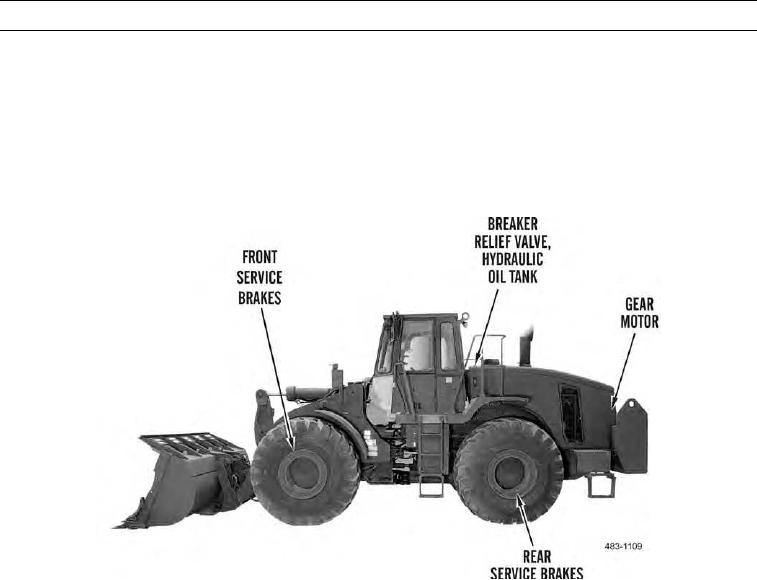
Piston pump supplies hydraulic oil required to operate brake and hydraulic fan system. Oil flows from pump to
control manifold. Control manifold includes a pressure relief valve, a shuttle valve, an inverse shuttle valve, a cut-
in valve, a cut-out valve, and a priority valve.
b.
Control manifold controls oil flow from pump to front and rear service brake accumulators. Control manifold also
controls oil flow to gear motor for hydraulic fan. A pressure relief valve located in control manifold limits oil pres-
sure that flows from pump.
0003 00-68