TM 5-3805-291-23-1
THEORY OF OPERATION - CONTINUED
0003 00
BRAKE AND HYDRAULIC FAN SYSTEM - CONTINUED
c.
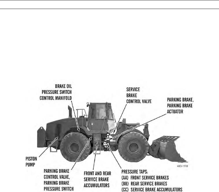
Control manifold contains a priority valve. When this valve is closed, oil flows to an inverse shuttle valve located
in control manifold. Oil then flows to front and rear service brake accumulators. When accumulators are charged,
priority valve opens. Oil then flows to gear motor for hydraulic fan system. A port in control manifold connects to
brake oil pressure switch. Brake oil pressure switch monitors oil pressure in brake accumulators. If oil pressure in
either brake accumulator drops below a minimum threshold, switch actuates.
d.
Brake accumulators contain a precharge of dry nitrogen. When oil flows into an accumulator, pressure oil moves
piston inside accumulator. Piston moves against charge of dry nitrogen gas. This puts compression on dry nitrogen
until oil pressure reaches cut-out pressure. Oil also flows to service brake control valve.
e.
Service brake control valve is in circuit from accumulators to service brakes. When a brake pedal is pushed, oil
from each accumulator flows to service brakes. Service brakes are then applied.
f.
When service brake control valve is released, lines from accumulators are blocked. Brake lines are connected to
drain port. This allows service brakes to release. Supply oil is then dumped back into hydraulic oil tank.
g.
Each brake application removes a quantity of oil from accumulators. Piston in each accumulator moves toward oil
end until oil pressure decreases to cut-in pressure. Control manifold then permits oil from pump to flow to brake
accumulators. This occurs until pressure increases to cut-out pressure.
h.
Hydraulic circuits for front and rear service brakes are completely separate. Applying force to a brake pedal causes
tandem spools in service brake control valve to move. This allows oil from both front and rear accumulators to
flow to disc brakes in each axle housing. Oil pressure causes wet disc brakes enclosed in each axle to engage. Heat
from brake friction is removed by oil in axle housings.
i.
Parking brake control valve connects to rear service brakes accumulator. Parking brake control valve can be actu-
ated by activating parking brake control switch (TM 5-3805-291-10).
0003 00-69

