
TM 5-3805-291-23-1
THEORY OF OPERATION - CONTINUED
0003 00
BRAKE AND HYDRAULIC FAN SYSTEM - CONTINUED
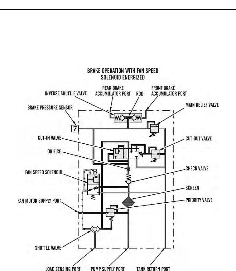
(b) Pump flow enters control manifold through load sensing port. Oil flow from pump flows through pri-
ority valve and exits supply port for fan motor. A small amount of pressurized oil flows through fan
speed solenoid, a pressure-reducing valve which assists in reducing pressure. If fan system pressure is
above pressure reducing pressure of fan speed solenoid, solenoid shifts to meter output pressure to
tank return port. Output pressure of fan speed solenoid is then reduced. Oil at a reduced pressure flows
to shuttle valve, which shifts right. Pressurized oil exits through load sensing port to upstroke pump.
427-C1766
0003 00-89