
TM 5-3805-291-23-1
THEORY OF OPERATION - CONTINUED
0003 00
BRAKE AND HYDRAULIC FAN SYSTEM - CONTINUED
(3)
Operation with Fan Speed Solenoid Energized.
(a) Fan system has priority when brake system pressure is at cut-out pressure. Fan speed solenoid controls
pump load sensing pressure when brake system is fully charged. Fan speed solenoid is a proportional
solenoid. As current to fan speed solenoid increases, output pressure decreases. When fan speed sole-
noid is energized, output pressure to pump load sensing port is at reduced. Thus, fan motor is turning
below maximum speed.
(b) Amount of current applied to fan speed solenoid is controlled by engine ECM using three inputs:
hydraulic oil temperature sensor, engine coolant temperature sensor, and inlet air manifold tempera-
ture sensor. If engine ECM determines that fan speed should be at minimum, maximum current is sent
to fan speed solenoid. If one of these three sensors shows there is a demand for more cooling, engine
ECM will reduce amount of current sent to fan speed solenoid. By decreasing current to fan speed
solenoid, pump will upstroke to provide more cooling capacity.
(c) Pump flow enters control manifold through load sensing port. Oil flow from pump flows through pri-
ority valve and exits supply port for fan motor. A small amount of pressurized oil flows through fan
speed solenoid, a pressure-reducing valve which assists in reducing pressure. If fan system pressure is
above pressure-reducing pressure of fan speed solenoid, solenoid shifts to meter output pressure to
tank return port. Engine ECM sends current to fan speed solenoid to further reduce output pressure.
Output pressure of fan speed solenoid is then reduced. Oil at a reduced pressure flows to shuttle valve,
which shifts right. Pressurized oil exits through load sensing port to meet system demands.
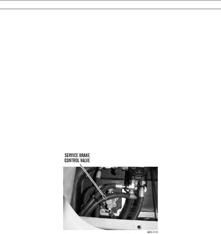
d.
Service Brake Control Valve.
0003 00-90