
TM 5-3805-291-23-1
THEORY OF OPERATION - CONTINUED
0003 00
BRAKE AND HYDRAULIC FAN SYSTEM - CONTINUED
(1)
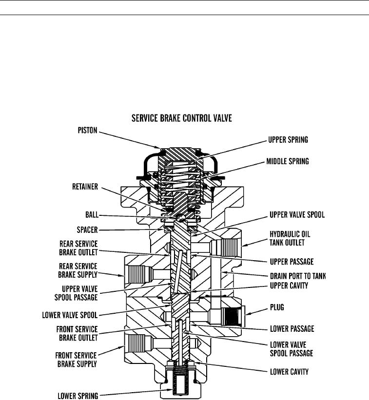
Service brake control valve is located on front right side underneath operator's platform. A mechanical
link connects two brake pedals to each other. When one brake pedal is depressed, a lever and cam assem-
bly actuates service brake control valve. Valve is a fully split modulating valve with two independent out-
put pressures.
(2)
Service brake control valve modulates pressurized oil flow between brake accumulators and service
brakes. Position of either brake pedal causes a specific pressure at service brakes. As pedal position
changes, pressure at service brake also changes.
427-C1768
(3)
When one brake pedal is depressed, a roller in brake pedal assembly pushes down on piston, which applies
a force on upper and middle springs. Spring force moves retainer and ball, causing upper valve spool to
move away from its seat in spacer.
(4)
Upper valve spool movement causes lower valve spool to move and compress lower spring. When valve
spools move, oil flow through upper and lower passages and tank drain port to hydraulic oil tank is
blocked.
0003 00-91