
TM 5-3805-291-23-1
ENGINE TESTS, INSPECTIONS, AND ADJUSTMENTS - CONTINUED
0010 00
FINDING TOP-CENTER POSITION FOR NO. 1 PISTON
0010 00
CAU T I ON
Never turn engine using crankshaft vibration damper. Crankshaft vibration damper is a precision part.
Major engine failure may be caused by damage to crankshaft vibration damper.
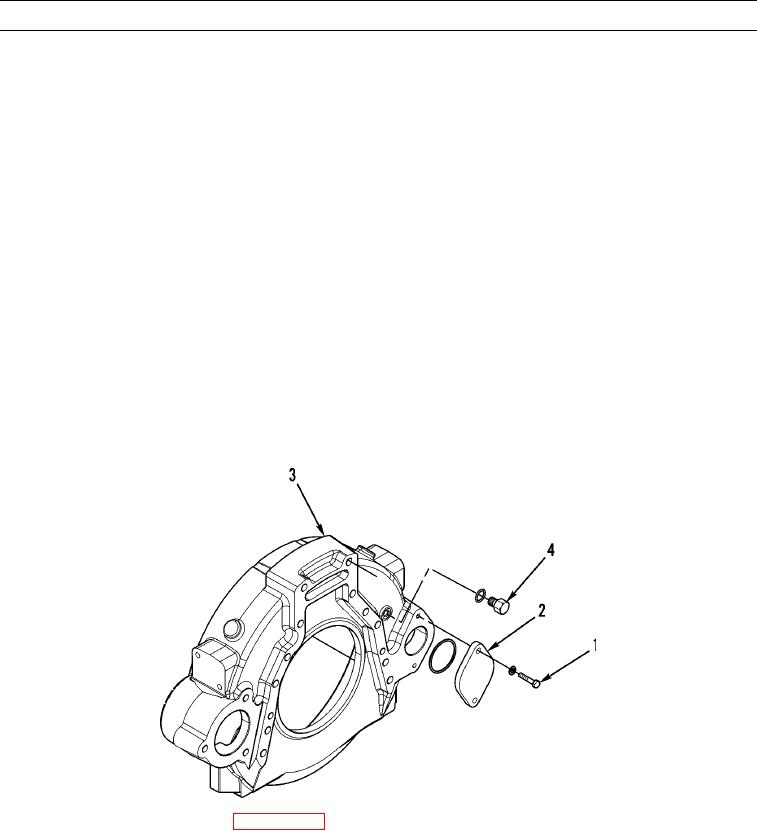
1.
Remove two bolts (1) and cover (2) from flywheel housing (3).
N OT E
Timing hole is located approximately 5.0 to 6.0 in. (127 to 152 mm) above turning hole in flywheel housing.
2.
Remove plug (4) from timing hole.
3.
Install timing pin with timing pin adapter in timing hole.
N OT E
Direction of engine rotation is counterclockwise,as the engine is viewed from the flywheel end. Turn
flywheel in direction of engine rotation.
If flywheel is turned beyond point of engagement with timing pin, turn flywheel clockwise approxi-
mately 30 degrees. Then turn flywheel counterclockwise until timing pin engages hole in flywheel. This
procedure removes play from gears when No. 1 piston is at top-center position.
4.
Turn flywheel until timing pin engages with hole in flywheel.
427-C0600
5.
Remove valve cover from engine (WP 0024 00).
0010 00-2