
TM 5-3805-291-23-1
TROUBLESHOOTING WITH A DIAGNOSTIC CODE - CONTINUED
0009 00
Table 8. Cycle Time Signal as a Function of Control Lever Position.
Lever
Position
Approximate Cycle Time
Tilt Lever
Full Forward Travel
10% to 15%
Tilt Lever
Full Rearward Travel
85% to 90%
Lift Lever
Full Forward Travel
10% to 15%
Lift Lever
Full Rearward Travel
85% to 90%
Auxiliary Lever
Full Forward Travel
10% to 15%
Auxiliary Lever
Full Rearward Travel
85% to 90%
Table 9. Cycle Time Signal as a Function of Control Lever Position.
Lever
Position
Approximate Cycle Time
Tilt Lever
Full Forward Travel
10% to 15%
Tilt Lever
Full Rearward Travel
85% to 90%
Lift Lever
Full Forward Travel
10% to 15%
Lift Lever
Full Rearward Travel
85% to 90%
Auxiliary Lever
Full Forward Travel
10% to 15%
Auxiliary Lever
Full Rearward Travel
85% to 90%
Table 10. Status for Kickout Set Switch.
Switch Position
J1-35 (wire H708-OR) Lift
J1-40 (wire H709-BU) Tilt
LIFT
Open
Ground
TILT
Ground
Open
OFF
Open
Open
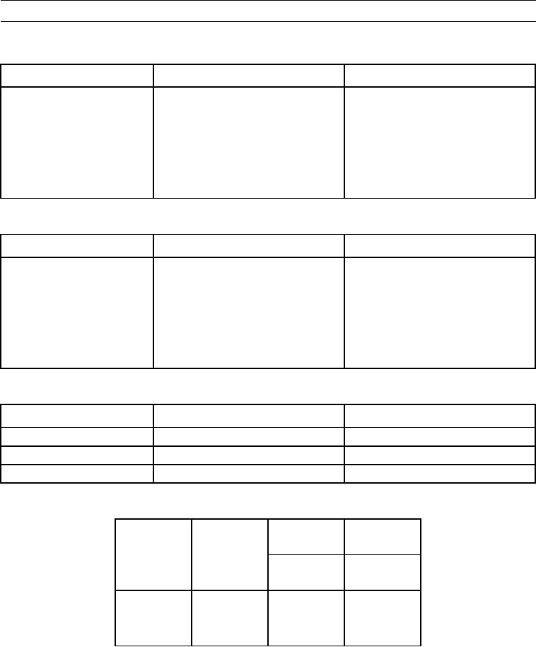
Table 11. Ride Control Switch Status.
G766-GN
G767-GN
Circuit
Circuit
Switch
J2-46
J2-45
Mode
Position
Input 1
Input 2
ON
Down
Open
Closed
OFF
Center
Closed
Closed
AUTO
Up
Closed
Open
0009 00-285