
TM 5-3805-291-23-1
TROUBLESHOOTING WITH A DIAGNOSTIC CODE - CONTINUED
0009 00
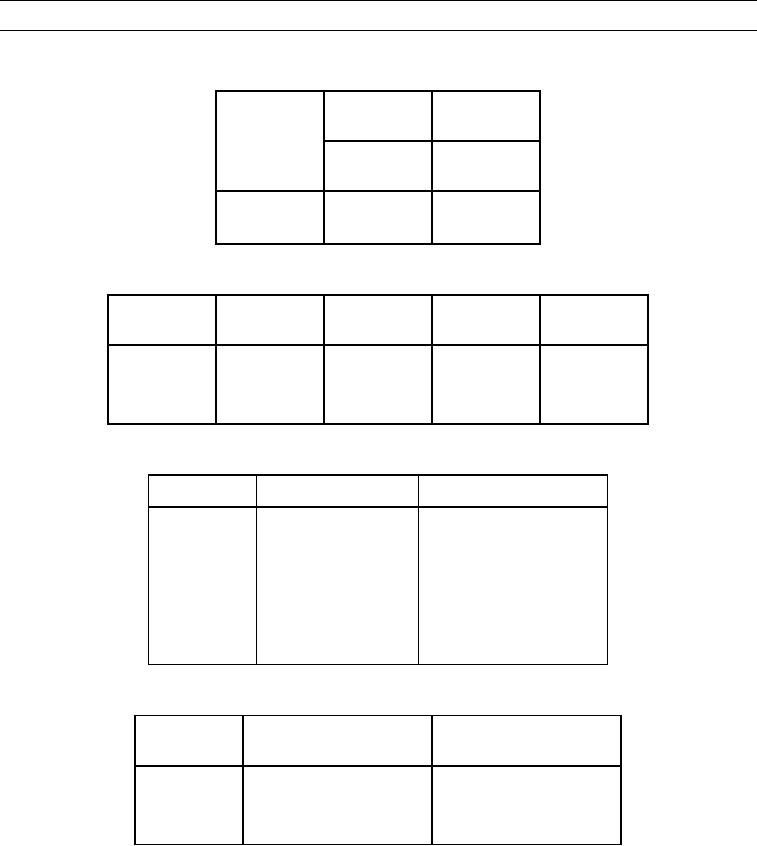
Table 12. Primary Steering Pressure Switch.
417-GY
484-YL
Circuit
Circuit
Switch
N/O
N/C
Position
J2-37
J2-45
Low Pressure
Open
Closed
High Pressure
Closed
Open
Table 13. Status for Transmission Direction Switch #2.
Switch
Position
J2-41
J2-40
J2-43
J2-42
Forward
Closed
Open
Closed
Open
Neutral
Closed
Open
Open
Closed
Reverse
Open
Closed
Open
Closed
Table 14. Duty Cycle Signal as a Function of Control Lever Position.
Lever
Position
Approximate Duty Cycle
Tilt Lever
Full Forward Travel
10% to 15%
Tilt Lever
Full Rearward Travel
85% to 90%
Lift Lever
Full Forward Travel
10% to 15%
Lift Lever
Full Rearward Travel
85% to 90%
Auxiliary Lever
Full Forward Travel
10% to 15%
Auxiliary Lever
Full Rearward Travel
85% to 90%
Table 15. Status for Kickout Set Switch.
Switch
Position
J1-35 (wire H708-OR) Lift
J1-40 (wire H709-BU) Tilt
LIFT
Open
Ground
TILT
Ground
Open
OFF
Ground
Ground
END OF WORK PACKAGE
0009 00-286