TM 5-3805-291-23-2
HOOD TILT SWITCH AND WIRING HARNESS REPLACEMENT - CONTINUED
0059 00
REMOVAL
1.
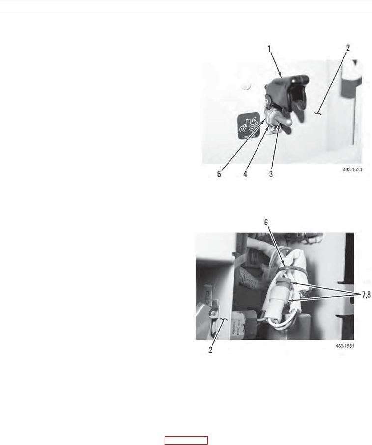
Remove nut (4), lockwasher (5), switch cover (1), and
toggle switch (3) from control box (2). Discard lock-
washer.
483-1530
2.
Cut and remove tiedown strap (6) from wiring har-
nesses (7 and 8). Discard tiedown strap.
3.
Disconnect chassis wiring harness (7) from tilt switch
wiring harness (8).
4.
Remove chassis wiring harness (7) from control box
(2).
483-1531
INSTALLATION
1.
Position chassis wiring harness (7) in control box (2).
2.
Connect chassis wiring harness (7) to tilt switch wiring harness (8).
3.
Install new tiedown strap (6) on wiring harnesses (7 and 8).
4.
Install toggle switch (3), switch cover (1), new lockwasher (5), and nut (4) on control box (2).
Install control box (Hood Tilt Relay Installation in WP 0053 00).
5.
6.
Verify system operation (TM 5-3805-291-10).
END OF WORK PACKAGE
0059 00-2

