
TM 5-3805-291-23-2
TILT KICKOUT POSITION SENSOR AND MOUNTING REPLACEMENT - CONTINUED
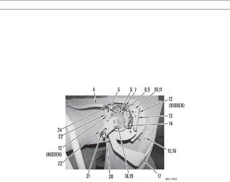
0089 00
REMOVAL - CONTINUED
2.
Disconnect wiring harness (4) from tilt kickout position sensor (6).
3.
Remove bolt (23), washer (5), clip (24), and spacer (12) from bracket (13).
4.
Remove two bolts (15), washers (16), and tilt arm (17) from machine.
5.
Remove bolt (21) and sleeve (20) from tilt arm (17).
6.
Remove two bolts (18), washers (19), and plate assembly (22) from tilt kickout position sensor (6).
7.
Remove five bolts (8), washers (9), clip (14), and tilt kickout position sensor (6) from bracket (13).
8.
Remove and discard tiedown strap (7) from tilt kickout position sensor (6).
9.
Remove two bolts (10), washers (11), spacers (12), and bracket (13) from machine.
483-1542
0089 00-3