
TM 5-3805-291-23-2
TRANSMISSION OIL COOLER LINES REPLACEMENT - CONTINUED
0102 00
INSTALLATION - CONTINUED
4.
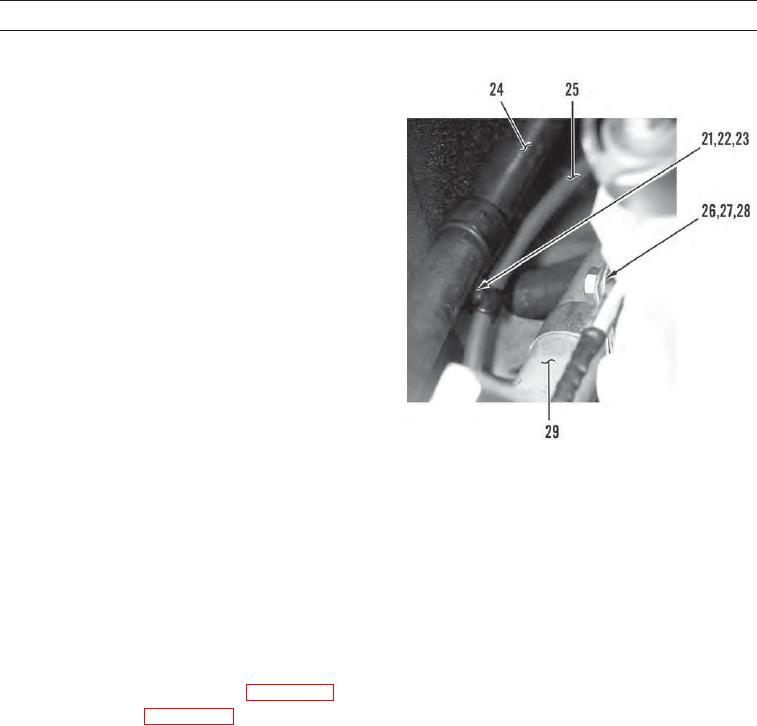
Position hydraulic lines (29) and install two clamps
(28), washer (27), and bolt (26) on machine.
5.
Position battery cable (25) and hose (24) and install
two clamps (23), washer (22), and bolt (21) on
machine.
427-C1940
6.
Connect test probe (20) to tube (7).
7.
Install new seal (18), two new O-rings (17), tube (6), flange (16), four washers (15), and bolts (14) on flange (19).
8.
Install clamp (13) on tube (7).
9.
Install washer (12) and bolt (11) on clamp (13).
10.
Instal clamp (10) on tube (6).
11.
Install washer (9) and bolt (8) on clamp (10).
12.
Install clamps (5 and 4) on tubes (7 and 6).
13.
Install washer (2), bolt (1), and nut (3) on clamps (5 and 4).
14.
Install oil cooler lines on oil cooler (WP 0205 00).
15.
Install side covers (WP 0135 00).
WAR N I N G
Before operating the machine, secure the steering frame lock in the stowed position. DO NOT operate
machine with steering frame lock connected. Failure to lock steering frame lock into the stowed position
before operating can result in loss of steering and injury or death to personnel.
16.
Secure steering frame lock in stowed position (TM 5-3805-291-10).
17.
Start machine (TM 5-3805-291-10).
18.
Run engine until operating temperature is reached and verify correct operation of machine (TM 5-3805-291-10).
19.
Shut down engine (TM 5-3805-291-10).
20.
Check for leaks.
END OF WORK PACKAGE
0102 00-5/(0102 00-6 Blank)