
TM 5-3805-291-23-2
PARKING BRAKE ACTUATOR REPLACEMENT - CONTINUED
0112 00
ADJUSTMENT - CONTINUED
Adjustment Procedure
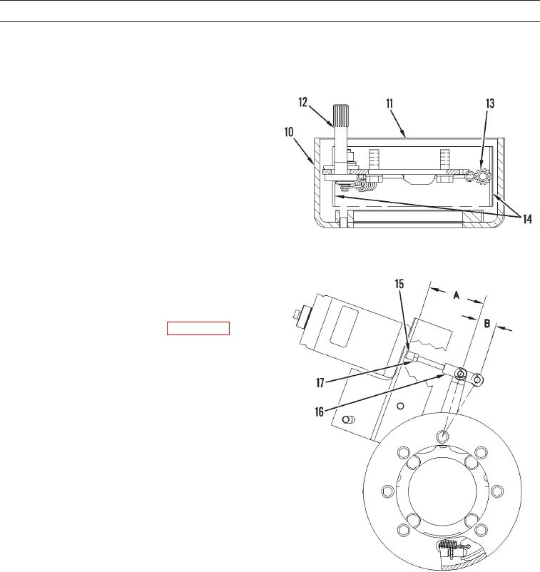
1.
Place brake drum (10) on a flat surface. Make sure that
large diameter of brake drum is facing upward. Place
brake group (11) into brake drum. Make sure that
camshaft (12) is facing upward.
2.
Rotate starwheel (13) in order to move brake
shoes (14) outward. Rotate starwheel until brake shoes
contact brake drum (10). Make sure that brake shoes
stay above radius at the bottom of brake drum.
3.
Rotate starwheel (13) so that brake shoes (14) press
against brake drum (10). The force of brake shoes
against brake drum should be sufficient to hold brake
shoes to brake drum when you lift brake group (11)
upward.
427-C1994
4.
Lift brake group (11) upward. Place brake drum (10)
and brake group on the flat surface.
5.
Rotate starwheel (13) for 15 clicks in order to release
the pressure of brake shoes (14) on brake drum (10).
6.
Install parking brake on machine (WP 0113 00).
7.
Apply the parking brake. Actuator shaft (15) should be
retracted.
8.
Adjust rod end (16) by turning the actuator shaft (15)
in order to achieve dimension (A) of 4.134 in.
(105 mm).
9.
Release parking brake in order to extend the actuator
shaft (15).
427-C1995
0112 00-4