
TM 5-3805-291-23-2
PARKING BRAKE ACTUATOR REPLACEMENT - CONTINUED
0112 00
ADJUSTMENT - CONTINUED
Adjustment Procedure - Continued
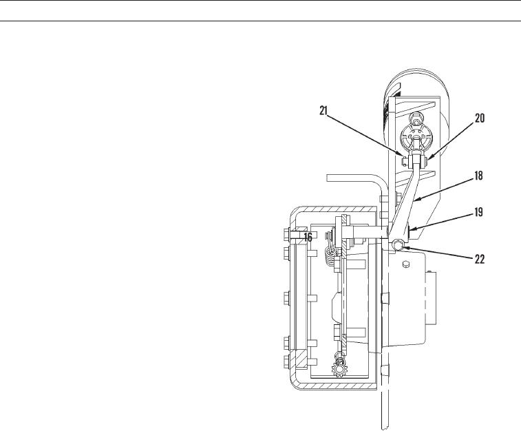
10.
Position lever (18) on splined end of camshaft (19).
Push lever so the brake camshaft will contact brake
shoes. Rotate actuator shaft (15) in order to align rod
end (16). Install pin (20). Tighten locknut (17) on
actuator shaft (15).
427-C1996
11.
Adjust lever (18) by removing lever from splined shaft (19). Rotate lever about splined
shaft (19) until dimension (B) equals 1.38 in. (35 mm).
12.
Install cotter (21) in pin (20).
13.
Install bolt (22).
14.
Apply parking brake (TM 5-3805-291-10).
N OT E
Replacement brake shoes must be burnished.
15.
In order to burnish brake shoes, make three successive stops from third speed forward at maximum speed. Allow park-
ing brake to cool to ambient temperature after third stop.
16.
Measure stroke of actuator. If dimension (B) exceeds 1.38 in. (35 mm), repeat steps 9 thru 13.
END OF WORK PACKAGE
0112 00-5/(0112 00-6 Blank)