
TM 5-3805-292-10
0004
OPERATOR CONTROLS AND INDICATORS CONTINUED
1
2
4
3
458-0868
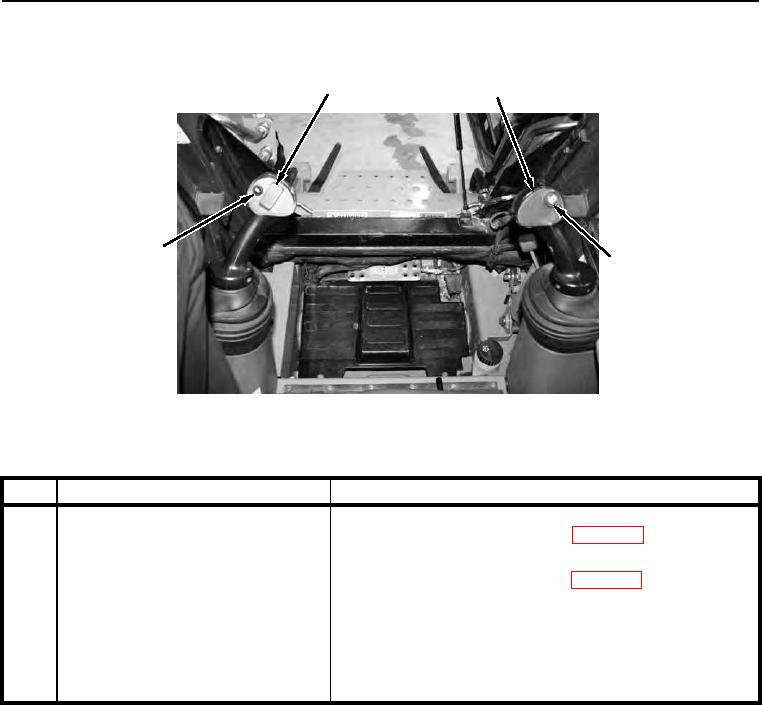
Figure 6. ISO Pattern Pilot Controls.
0004
KEY
COMPONENT
DESCRIPTION
1
Left-Hand (Ground Drive) Control
Steering and travel are controlled with this lever. Refer to
Lever
Operation Under Usual Conditions (WP 0005).
2
Right-Hand (Loader) Control Lever
Controls movement of lift arm up, down, and float. Refer to
Operation Under Usual Conditions (WP 0005).
3
Right Control Handle Parking Brake
Red pushbutton is located on right control lever. Releases
Button
parking brake after first using the parking brake button on the
DIP. DO NOT activate parking brake while machine is moving.
Stop machine and then set the brake.
4
Horn Button
Activates horn. Located on front side of left control lever.