TM 5-3805-292-23
0007
ENGINE CONTINUED
Fuel Supply System Check - Continued
0007
e. Operate engine to purge any air which entered system during gauge installation (TM 5-3805-292-10).
f.
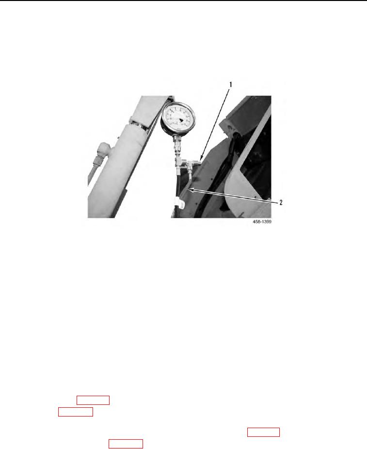
Check for air in system by holding button (Figure 3, Item 1) in and observing fuel in clear tubing
(Figure 3, Item 2).
Figure 3. Checking For Air In System.
0007
3. When air is no longer visible in clear test line, measure and record operating pressure, while continually
observing for air in fuel.
a. Fuel pressure specification between fuel filter and injection pump is 4 to 10 psi (0.276 to 0.689 bar).
b. Measure pressure under the following conditions:
(1) Pressure at low idle; no load on engine.
(2) Pressure at high idle; no load on engine.
(3) With assistance, close ROPS. Run gauge through ROPS panel.
(4) Pressure at high idle; apply load to engine using hydraulics (over relief) or hydrostatic stall. Load
engine to 1,400 RPM (TM 5-3805-292-10).
4. Tilt ROPS. Shut off engine (TM 5-3805-292-10).
5. Remove fuel pressure tester and connect lines.
6. Remove male and female quick connect from fuel system.
7. If fuel pressure is below 4 psi (0.276 bar) at any time during tests, the possible causes/repairs are:
a. Inline fuel filter (WP 0016).
b. Fuel filter (WP 0041).
c.
Lines and connections from fuel filter inlet back to fuel tank. Check for damaged lines (kinks create restric-
tion; rub marks may allow air to enter) and leakage at O-ring fittings (WP 0017).
d. Drain and clean fuel tank (WP 0008).
e. Fuel tank cap. Be sure a vacuum is not being formed in fuel tank. A vacuum at tank would reduce fuel sup-
ply pressure to injection fuel pump inlet. Vacuum in fuel tank might not be observable during short-term
running.

