
TM 5-3805-292-23
0011
ALTERNATOR INSTALLATION CONTINUED
N OT E
Install wires and electrical connectors as tagged during removal.
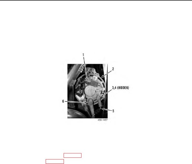
6. Connect electrical connector (Figure 9, Item 1) to alternator (Figure 9, Item 2).
7. Install two wires (Figure 9, Item 5), new lockwashers (Figure 9, Item 4), and nuts (Figure 9, Item 3) on alterna-
tor (Figure 9, Item 2). Position boots (Figure 9, Item 6) over wires.
Figure 9. Alternator Rear View.
0011
END OF TASK
FOLLOW-ON TASKS
00011
1. Install fan, fan guard, and shroud (WP 0015).
2. Connect battery power (WP 0143).
3. Verify correct operation of machine (TM 5-3805-292-10).
END OF TASK
END OF WORK PACKAGE
0011-9/(10 blank)