• Home
  • Download PDF
  • Order CD-ROM
  • Order in Print
Figure 6. Mounting Bracket Assembly.
Figure 8. Alternator Front View.

Field Maintenance Manual For M400T And M400W
Page Navigation
  167    168    169    170    171  172  173    174    175    176    177  
img
.
TM 5-3805-292-23
0011
MOUNTING BRACKET INSTALLATION CONTINUED
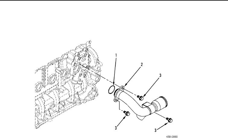
2. Position new O-ring (Figure 7, Item 1) and pipe (Figure 7, Item 2) on machine and install three bolts (Figure 7,
Item 3).
Figure 7. Engine Oil Cooler Pipe.
0011
END OF TASK
0011-7


Privacy Statement
Press Release
Contact

© Copyright Integrated Publishing, Inc.. All Rights Reserved.