
TM 5-3805-292-23
0042
INSTALLATION
00042
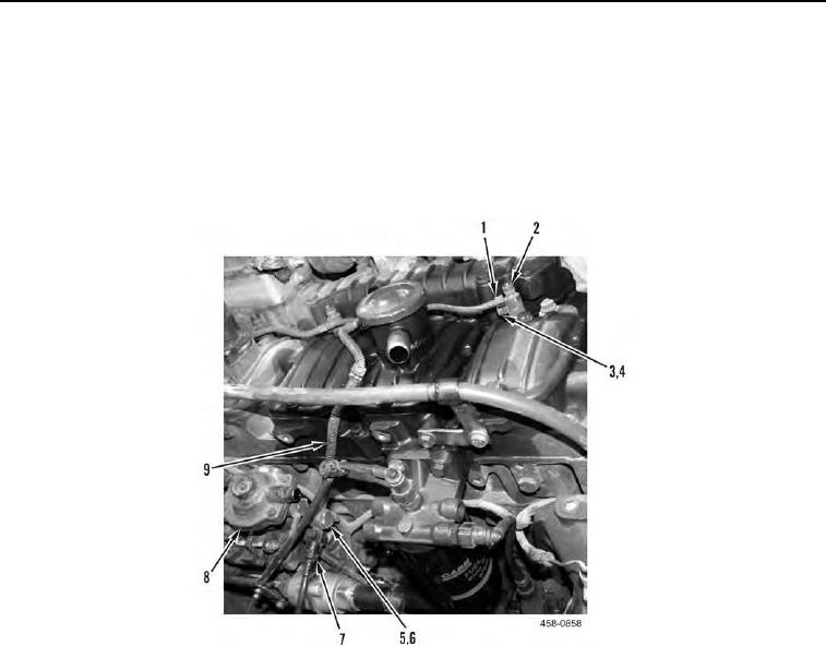
1. Position tube (Figure 5, Item 9) on machine.
2. Install four new gaskets (Figure 5, Item 4), fuel return pipe (Figure 5, Item 1), and four bolts (Figure 5, Item 3)
on fuel injector (Figure 5, Item 2).
3. Install two new gaskets (Figure 5, Item 6), tube (Figure 5, Item 9), and bolt (Figure 5, Item 5) on fuel injection
pump (Figure 5, Item 8).
4. Connect fuel return line (Figure 5, Item 7) to tube (Figure 5, Item 9).
Figure 5. Fuel Return Pipe.
0042