
TM 5-3805-292-23
0042
INSTALLATION CONTINUED
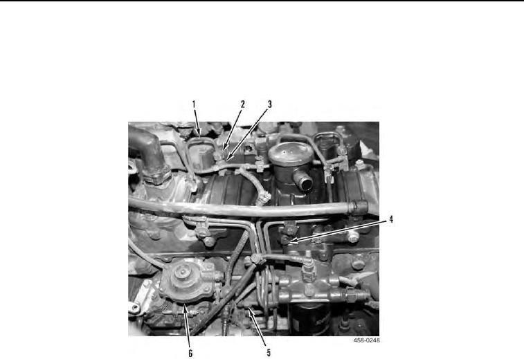
5. Install fuel injection tube assembly (Figure 6, Item 1) and two bolts (Figure 6, Item 4) on machine.
6. Connect four fittings (Figure 6, Item 5) to fuel injection pump (Figure 6, Item 6).
7. Connect four fittings (Figure 6, Item 2) to fuel injectors (Figure 6, Item 3).
Figure 6. Fuel Injection Tube Assembly.
0042